Bobbin replacing mechanism for winder

A winding machine and bobbin yarn technology, which is applied in the field of bobbin changing mechanism for winding machines, can solve the problems of high price, complicated structure, and high labor intensity, and achieve the effects of low manufacturing cost, simple overall structure, and convenient operation for workers

Pending Publication Date: 2020-01-03
苏州济洋纺织机械有限公司
View PDF0 Cites 1 Cited by
  • Summary
  • Abstract
  • Description
  • Claims
  • Application Information

AI Technical Summary

Problems solved by technology

[0002] In market applications, automatic winders are suitable for spinning varieties that require high yarn quality due to their multiple functions. However, this type of winder consumes a lot of energy, and the price of the winder is also very expensive. no small burden
The existing domestic ordinary winder has low energy consumption, applicable functions and low price, but the degree of automation is poor and the labor is much
In automation, an

Method used


Image

  • Bobbin replacing mechanism for winder
  • Bobbin replacing mechanism for winder

Examples


Embodiment 1

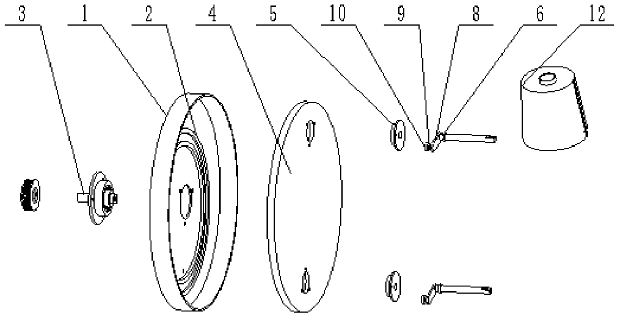
[0016] Example 1 as figure 1 As shown, a bobbin changing mechanism for a winding machine includes a vertically fixed disc-shaped track disc 1, and two concentric tracks 2 are fixed inside the track disc 1, and the outer track 2 and the track disc 1 The bottom of the inner wall is tangent, and the center of the orbital disk 1 is rotated by a bearing to provide a main shaft 3. The main shaft 3 is located on the side of the orbital disk 1 where the track 2 is provided. A turntable 4 is fixed on the side. A through hole is installed, and a support seat 5 is embedded in the through hole on the turntable 4 .

[0017] A mounting hole is provided in the support seat 5, and a bobbin lifting rod 6 is arranged in the mounting hole of the supporting seat 5. The end of the bobbin lifting rod 6 close to the track disk 1 is provided with a driving part 8 arranged perpendicularly thereto, and the driving part 8 is far away from the One end of the bobbin picker bar 6 is fixedly provided with ...

Embodiment 2

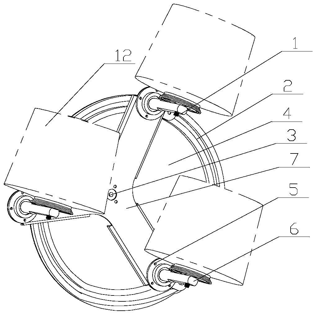
[0019] Embodiment 2 provides a bobbin changing mechanism for a bobbin winder, the whole is roughly the same as that of Embodiment 1, the difference is that figure 2 As shown, three installation through holes are evenly distributed around the circumference of the main shaft 3 on the turntable 4 . In addition, the turntable 4 is provided with a reinforcing plate 7 on one side of the track 2 , and the reinforcing plate 7 is provided with avoidance through holes corresponding to the positions of the support seats 5 and the main shaft 3 .

[0020] When working: the worker vertically loads the bobbin yarn on the installation rod 11 located on the upper side of the turntable 4, the power device drives the turntable 4 to rotate through the main shaft 3, and the turntable 4 drives the bobbin lifting rod 6 and sliding The block 8 slides along the track 2, because the distance between the installation through hole and the top end of the track 2 when the installation through hole on the ...


PUM


Abstract

The invention discloses a low-cost bobbin replacing mechanism for a winder. The bobbin replacing mechanism comprises a disc-shaped rail disc which is vertically and fixedly arranged, two rails which are in a concentric circle shape are fixedly arranged in the rail disc, moreover, the outer side rail is tangent to the bottom of the inner wall of the rail disc, a main shaft is rotationally arrangedat the circle center of the rail disc through a bearing, a rotating disc is fixedly arranged on the main shaft and located on the side, provided with the rails, in the rail disc, at least two mountingthrough holes are uniformly distributed in the rotating disc in the circumferential direction of the main shaft, bobbin yarn picking rods are rotatably arranged in the mounting through holes of the rail disc, the ends, close to the rail disc, of the bobbin yarn picking rods are provided with driving parts which are arranged perpendicular to the bobbin yarn picking rods, clamping blocks are fixedly arranged at the ends, far away from the bobbin yarn picking rods, of the driving parts, the distance between the center of each mounting through hole and the center of the corresponding clamping block is equal to the distance between the center of the rails and the center of the rotating disc, the clamping blocks are movably clamped between the rails which are in the concentric circle shape, theends, away from the rail disc, of the bobbin yarn picking rods are provided with mounting rods for loading bobbin yarn, and a power device is connected on the main shaft and located on the side, awayfrom the rotating disc, of the rail disc.

Description

technical field [0001] The invention relates to the textile field, in particular to a bobbin changing mechanism for bobbin winding machines. Background technique [0002] In market applications, automatic winders are suitable for spinning varieties that require high yarn quality due to their multiple functions. However, this type of winder consumes a lot of energy, and the price of the winder is also very expensive. No small burden. The existing domestic common winder has low energy consumption, applicable functions and low price, but the degree of automation is poor and it requires a lot of labor. In automation, an important function is the automatic bobbin change. When the yarn is wound, the spare bobbin is ready and enters the bobbin changing. Keep vertically upward during the movement, but the structure is complex and expensive. However, ordinary winding machines can only be changed manually by workers, and the changing position is at the bottom, so they can only bend...

Claims


Application Information

Patent Timeline
IPC IPC(8): B65H67/06
CPCB65H67/06B65H2701/31
Inventor 曹明
Owner 苏州济洋纺织机械有限公司
Why Eureka
Try Eureka