A kind of melt blown fiber and its preparation method and application
A melt-blown fiber and melt-blown technology, applied in the field of melt-blown fiber and its preparation, can solve problems such as difficult diameter ranges
- Summary
- Abstract
- Description
- Claims
- Application Information
AI Technical Summary
Problems solved by technology
Method used
Image
Examples
preparation example Construction
[0043] [Preparation method of melt-blown fiber]
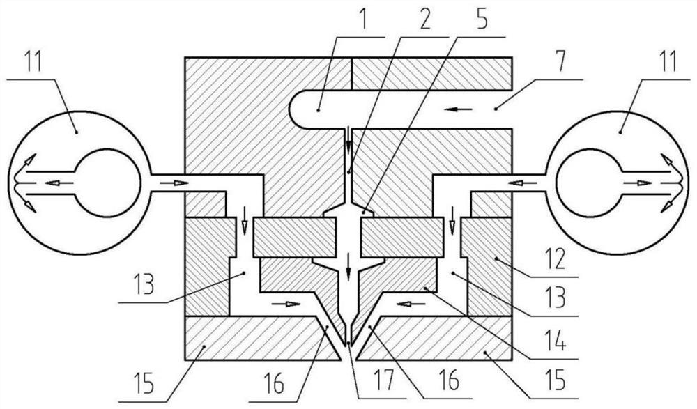
[0044] As mentioned above, the present invention provides the preparation method of above-mentioned melt-blown fiber, and described method is based on melt-blown device; Fluid devices;
[0045] The spinning assembly includes a distribution plate and a spinneret; the spinneret forms spinneret holes for melt ejection; the spinneret, distribution plate and air knife form a draft hot air flow channel for heat Air circulation; the air knife and spinneret form an air gap slit for accelerating hot air and ejecting it;
[0046] The balance cavity at the bottom of the hanger-shaped spinning die communicates with the spinneret hole formed by the spinneret in the spinning assembly, and the outlet end of the device for uniformly distributing the fluid is connected to the distribution plate and the spinneret in the spinning assembly One end of the drafting hot gas flow channel formed by the air knife communicates with the other end of the...
Embodiment 1
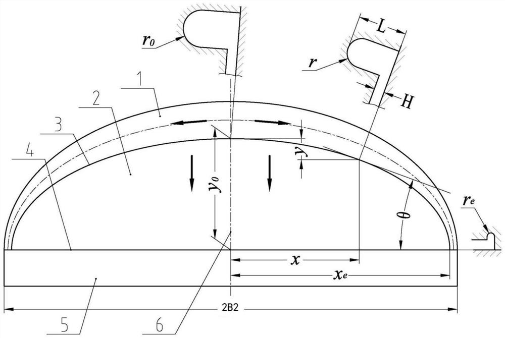
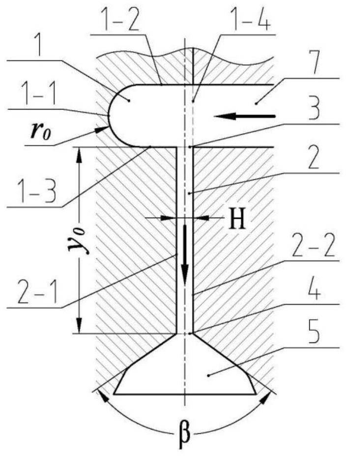
[0133] Such as figure 1 and 2 As shown, a clothes hanger-shaped spinning die flow channel structure for evenly distributing the melt, the die flow channel structure includes a manifold 1 and a slit flow channel 2; the manifold 1 is arranged in the slit flow the upper part of road 2;
[0134] Wherein, the manifold 1 is in the shape of a clothes hanger; the manifold 1 is a horizontal U-shaped structure, and the horizontal U-shaped structure includes a bottom end 1-1, a first side wall 1-2 of the manifold, a second manifold Two side walls 1-3 and the third side wall 1-4 of the manifold, the bottom end 1-1 of the horizontal U-shaped structure is a semicircular structure with a radius r, and the first side wall 1-2 of the manifold One end is connected tangentially to one side of the bottom end 1-1 of the horizontal U-shaped structure, and the other end of the first side wall 1-2 of the manifold is vertically connected to the third side wall 1-4 of the manifold , one end of the s...
Embodiment 2
[0152] Such as figure 1 and figure 2 As shown, the present embodiment provides a clothes-hanger-shaped spinning die, which includes the runner structure of the clothes-hanger-shaped spinning die in Embodiment 1; the clothes-hanger-shaped spinning die also includes a feed pipe, and the feed The pipe communicates with the feed port on the third side wall 1-4 of the manifold of the horizontal U-shaped structure; the feed pipe is used to connect external equipment and transport the melt into the manifold 1; the hanger-shaped The spinning die head also includes a balance cavity 5 which communicates with the outlet 4 of the slit channel.
[0153] In a preferred embodiment of the present invention, the shape of the balance chamber 5 is not particularly limited, it can be a cavity with a specific volume, the upper end of the balance chamber communicates with the outlet of the slit flow channel, and the balance chamber The lower end can communicate with other spinning components; th...
PUM
| Property | Measurement | Unit |
|---|---|---|
| diameter | aaaaa | aaaaa |
| diameter | aaaaa | aaaaa |
| diameter | aaaaa | aaaaa |
Abstract
Description
Claims
Application Information
 - R&D
- Intellectual Property
- Life Sciences
- Materials
- Tech Scout
- Unparalleled Data Quality
- Higher Quality Content
- 60% Fewer Hallucinations
Browse by: Latest US Patents, China's latest patents, Technical Efficacy Thesaurus, Application Domain, Technology Topic, Popular Technical Reports.
© 2025 PatSnap. All rights reserved.Legal|Privacy policy|Modern Slavery Act Transparency Statement|Sitemap|About US| Contact US: help@patsnap.com


