Bluetooth headset and temperature screening circuit therein

A technology of bluetooth earphones and circuits, applied in earpiece/earphone accessories, electrical components, loudspeakers, etc.

Pending Publication Date: 2020-01-03
广东思派康电子科技有限公司
View PDF0 Cites 1 Cited by
  • Summary
  • Abstract
  • Description
  • Claims
  • Application Information

AI Technical Summary

Problems solved by technology

[0003] In the above structure, the Bluetooth chip needs to consume two detection pins to connect two NTC resistors respectively. Due to the tight pin resources of the Bluetooth chip itself, consuming two detection pins is too extravagant. Therefore, it is urgent to develop a temperature screening circuit to Auxiliary Bluetooth chip temperature detection, in order to achieve the purpose of saving Bluetooth chip pin resources

Method used


Image

  • Bluetooth headset and temperature screening circuit therein
  • Bluetooth headset and temperature screening circuit therein

Examples


Embodiment 1

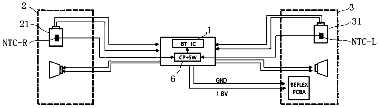
[0023] The bluetooth earphone of this embodiment is as figure 1 As shown, the bluetooth chip 1, the left earphone 2 and the right earphone 3 are included, the left earphone 2 and the right earphone 3 are respectively equipped with batteries 21, 31, and the power supply lines of the batteries 21, 31 are respectively provided with NTC thermistors. The voltage divider circuit connects the voltage divider contacts NTC-R and NTC-L of the two voltage divider circuits to the Bluetooth chip 1 through the temperature screening circuit 6, wherein the voltage divider contacts are used to collect the temperature data of the NTC thermistor, so Called the temperature collection point.

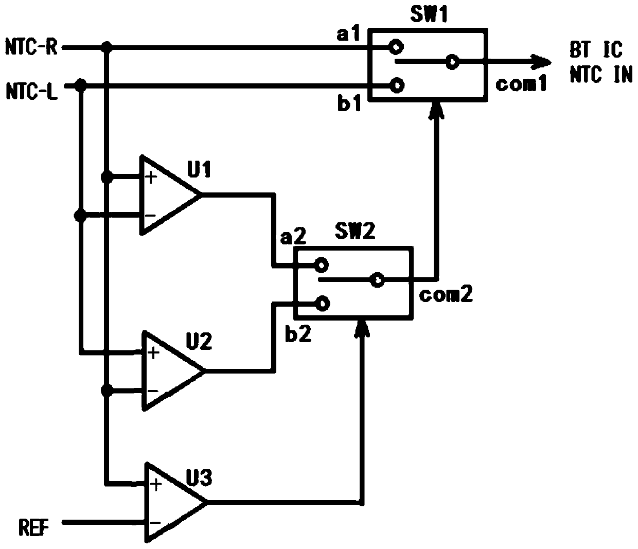
[0024] temperature screening circuit 6 as figure 2 As shown, it consists of three comparators U1, U2, U3 plus two dual-stage electric control switches SW1, SW2, where the temperature collection point NTC-R is respectively connected to the positive input terminal of comparator U1, comparator U2 The negativ...

Embodiment 2

[0037] Embodiment 2 On the basis of Embodiment 1, the positive input terminal of the comparator U3 is changed to be connected to the temperature collection point NTC-L, and the function of the temperature screening circuit in Embodiment 1 is also realized.

[0038] It should be noted that, as a secondary option, the positive input terminal of the comparator U3 can be changed to connect the temperature collection points NTC-R and NTC-L respectively, so that the temperature collection points NTC-R and NTC-L can control the comparison The output of the comparator U3, but this solution will cause the output level of the comparator U3 to jump quickly and increase the power consumption, so it can be selected according to actual needs.

Embodiment 3

[0040] Embodiment 3 On the basis of Embodiment 1, the NTC thermistor is used as a PCT thermistor instead, and the negative input terminal of the comparator U3 is changed to connect the PCT thermistor, and the positive input of the comparator U3 changed to the input reference voltage V REF , the function of the temperature screening circuit in Embodiment 1 is also realized.


PUM


Abstract

The invention relates to a temperature screening circuit. The temperature control circuit comprises comparators U1, U2 and U3, multistage electric control switches SW1 and SW2 and two temperature acquisition points used for acquiring output voltage of a temperature sensing device, wherein one temperature acquisition point is respectively connected with the non-inverting input end of the comparatorU1 and the inverting input end of the comparator U2, and the other temperature acquisition point is respectively connected with the inverting input end of the comparator U1 and the non-inverting input end of the comparator U2; the output end of the comparator U3 is connected with the controlled end of the multi-stage electric control switch SW2; the output ends of the comparator U1 and the comparator U2 are respectively connected with two wiring ends of a multi-stage electric control switch SW2, and the output end of the multi-stage electric control switch SW2 is connected with the controlledend of a multi-stage electric control switch SW1, and two temperature acquisition points are respectively connected with two wiring ends of the multi-stage electric control switch SW1; and if the voltage output by the temperature sensing device is negatively correlated with the temperature, the reverse input end of the comparator U3 is used for receiving the reference voltage, and the same-direction input end of the comparator U3 is connected with the temperature acquisition point, and otherwise, the connection method of the input end of the comparator U3 is opposite.

Description

technical field [0001] The invention relates to temperature detection of earphone batteries, in particular to a bluetooth earphone and a temperature screening circuit therein. Background technique [0002] In order to improve battery life, existing bluetooth earphones are equipped with batteries on its left and right earphones. When the temperature of any one of the batteries exceeds the allowable temperature range, the Bluetooth chip will perform corresponding controls, such as charge and discharge control, and shutdown control, etc., so that Realize the protection function. [0003] In the above structure, the Bluetooth chip needs to consume two detection pins to connect two NTC resistors respectively. Due to the tight pin resources of the Bluetooth chip itself, consuming two detection pins is too extravagant. Therefore, it is urgent to develop a temperature screening circuit to Auxiliary Bluetooth chip temperature detection, in order to achieve the purpose of saving Blu...

Claims


Application Information

Patent Timeline
Patent Type & Authority Applications(China)
IPC IPC(8): H04R1/10
CPCH04R1/1091H04R2201/10
Inventor 孙成友张鑫王贤明
Owner 广东思派康电子科技有限公司
Why Eureka
Try Eureka