Supercharge Your Innovation With Domain-Expert AI Agents!

Design method for stamping die for machining dustproof cover

A technology of stamping die and design method, which is applied in the design field of stamping die for processing dust cover, can solve the problems of affecting the production progress, increasing the blanking gap, and scrapping the die, so as to ensure normal use, avoid inner diameter out of tolerance, The effect of uniform pressure

Active Publication Date: 2020-01-07
LUOYANG BEARING RES INST CO LTD
View PDF6 Cites 0 Cited by
  • Summary
  • Abstract
  • Description
  • Claims
  • Application Information

AI Technical Summary

Problems solved by technology

At this time, the outer diameter of the punching die used to stamp the inner diameter of the dust cover in the stamping die is within the tolerance range. If the outer diameter of the punching die is reduced to reduce the inner diameter of the dust cover If the diameter is ground, the blanking gap will increase, and the mold will not be able to punch out excess material, which will cause the mold to be scrapped, which will increase the production cost and affect the production progress.
[0004] Therefore, when designing the stamping die for this type of dust cover, the outer diameter of the punching die cannot be determined blindly according to the size of the product drawing or the method of grinding the outer diameter of the punching die. The influence of bending deformation on the size should be considered. This brings great difficulty to the mold design

Method used


Image

  • Design method for stamping die for machining dustproof cover
  • Design method for stamping die for machining dustproof cover
  • Design method for stamping die for machining dustproof cover

Examples


Embodiment Construction

[0034] The technical solution of the present invention will be clearly and completely described below in conjunction with specific embodiments. Apparently, the described embodiments are only a part of the embodiments of the present invention, not all of them. Based on the embodiments of the present invention, all other embodiments obtained by persons of ordinary skill in the art without making creative efforts belong to the protection scope of the present invention.

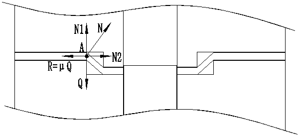
[0035] Please refer to figure 1 , figure 1Schematic diagram of the structure of the dust cover. A through hole is provided in the middle part of the dustproof cover, and the dustproof cover includes an outer sealing section matched with the outer ring of the bearing, an inner sealing section matched with the inner ring of the bearing, and an inclined connecting section connecting the outer sealing section and the inner sealing section. It should be noted that, in the present invention, the forming process of th...


PUM


Abstract

The invention discloses a design method for a stamping die for machining a dustproof cover. The design method comprises the following steps that the stamping die comprises an upper die body and a lower die body, wherein the upper die body comprises an upper die base and a forming male die; the lower die body comprises a lower die base, a stepped cylinder punching die, an annular forming female dieand a blanking female die; an upper cylinder of the punching die is sleeved with the forming female die, the forming female die can slide up and down along the upper cylinder, and the outer diameterof the forming male die and the forming female die can be determined according to the outer diameter of the dustproof cover; the upper die comprises a first rubber ring, the lower die comprises a second rubber ring, and then the size of the rubber rings is determined; a groove is formed in the bottom of the forming male die, and the groove is matched with the punching die to punch the inner diameter of the dustproof cover; and the outer diameter of the punching die can be determined according to the influence of the set inner diameter of the dustproof cover and the bending stress. According tothe design method, on the basis of considering the influence of bending deformation on the inner diameter of the dustproof cover, the size of the rubber rings and the outer diameter of the punching die are calculated, normal use of the die is guaranteed, and the overproof inner diameter of the dustproof cover is avoided.

Description

technical field [0001] The invention relates to the technical field of die design, in particular to a design method of a stamping die for processing a dust cover. Background technique [0002] The dust cover is one of the accessories of the rolling bearing. The bearing with the dust cover is generally used in the working conditions with severe dust. It is widely used. The dust cover plays a role in preventing the dust from entering the inside of the bearing. In the industry, the dust cover is generally processed by stamping, so its size is guaranteed by the size of the mold. [0003] For the dust cover with small plate thickness (such as figure 1 As shown), the design only needs to design the size of the mold according to the product size, but for the dust cover with large plate thickness and small inner diameter platform, it is found in the actual processing process that when the mold size is designed according to the product size, there will be The phenomenon that the in...

Claims


Application Information

Patent Timeline
Patent Type & Authority Applications(China)
IPC IPC(8): B21D37/12B21D45/08B21D53/80
CPCB21D37/12B21D45/08B21D53/80
Inventor 马延波
Owner LUOYANG BEARING RES INST CO LTD
Features
  • R&D
  • Intellectual Property
  • Life Sciences
  • Materials
  • Tech Scout
  • Unparalleled Data Quality
  • Higher Quality Content
  • 60% Fewer Hallucinations
Learn More