
New energy motor rotor magnetic steel feeding assembly mechanism

A technology of motor rotor and assembly mechanism, applied in electromechanical devices, manufacturing of motor generators, manufacturing of stator/rotor body, etc., can solve problems such as insufficient flexibility, low efficiency, singleness, and need to do servo rotation below, to avoid beats Waste, reduce friction, provide work efficiency effects

Active Publication Date: 2020-01-07
COMAU SHANGHAI ENG
View PDF6 Cites 3 Cited by
  • Summary
  • Abstract
  • Description
  • Claims
  • Application Information

AI Technical Summary

Problems solved by technology

Pneumatic or servo slides are placed above the rotor. The distribution of magnetic steel slots on the rotor is a figure of eight or one. If the figure of eight is installed in one direction, and the installation direction is single, servo rotation is required below. It is a figure-eight arrangement, so a mechanism for installing magnets can only meet the needs of magnet slots in one direction, and another set of magnet insertion mechanisms must be made to cooperate with it, and the flexibility is not good enough
There are many places to use robots to fetch magnets, and the flexibility is good, but basically it is a piece of magnets to fetch materials, and the efficiency is low

Method used


Image

  • New energy motor rotor magnetic steel feeding assembly mechanism
  • New energy motor rotor magnetic steel feeding assembly mechanism
  • New energy motor rotor magnetic steel feeding assembly mechanism

Examples


Embodiment Construction

[0019] The present invention will be further described below in conjunction with specific embodiments. It should be understood that these examples are only used to illustrate the present invention and not to limit the scope of the present invention. In addition, it should be understood that after reading the content taught by the present invention, those skilled in the art can make various changes or modifications to the present invention, and these equivalent forms also fall within the scope defined by the appended claims of the present application.

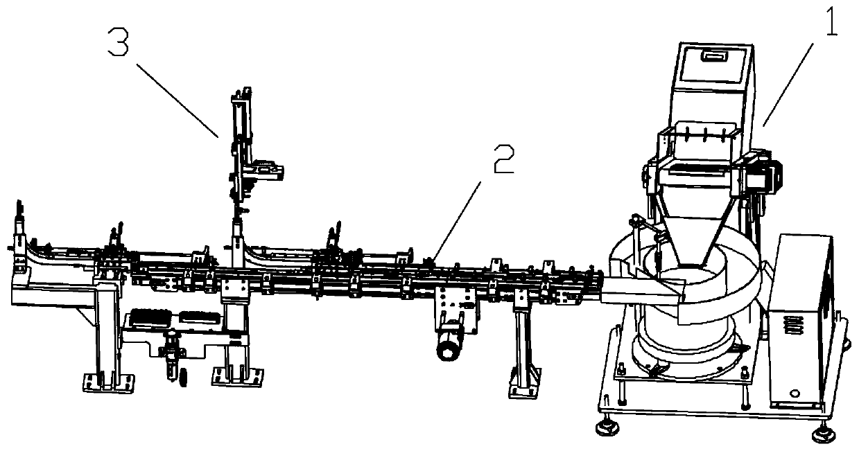
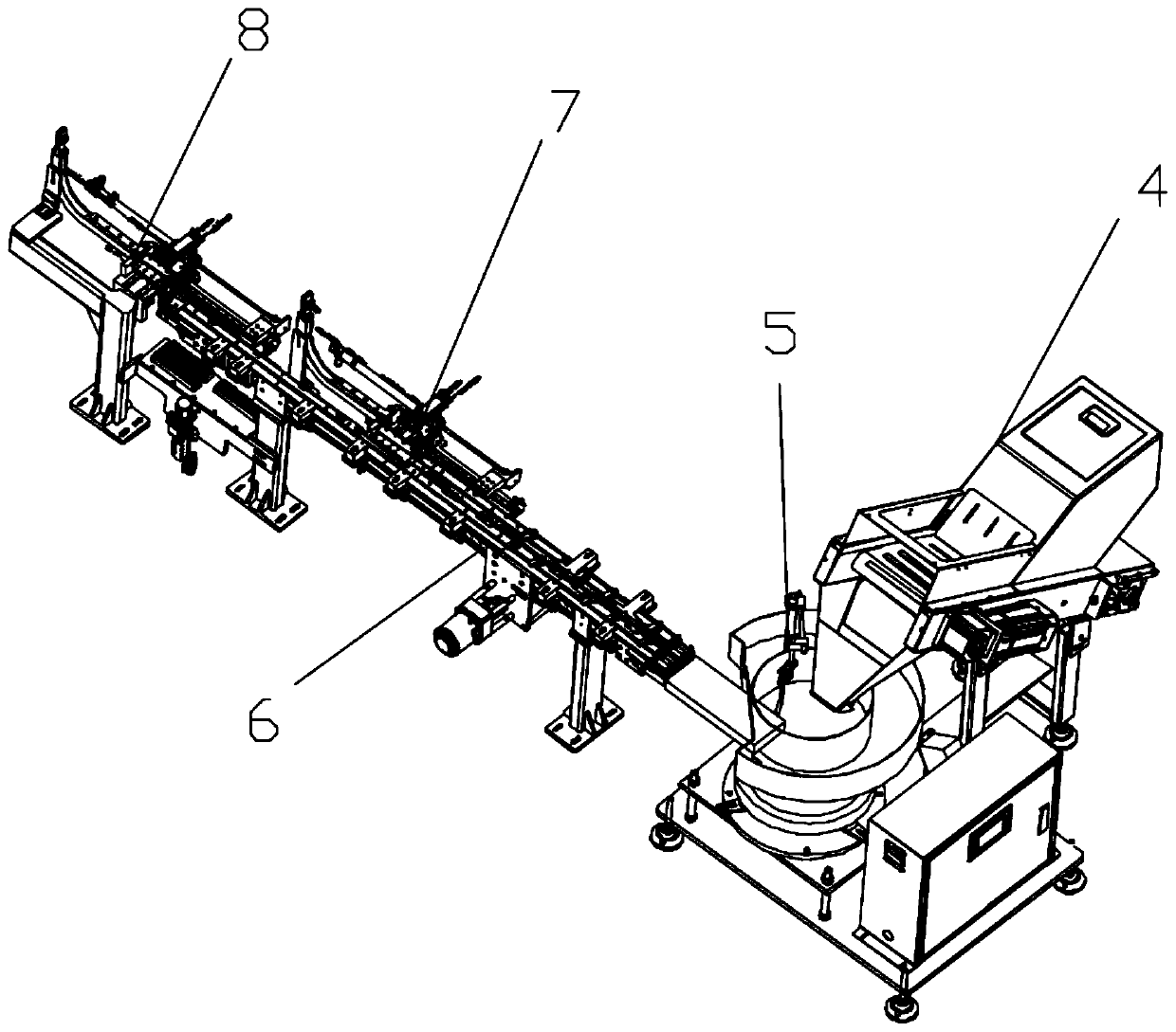
[0020] like figure 2 As shown, a new energy motor rotor magnetic steel loading assembly mechanism disclosed by the present invention generally includes three parts: the front section 1 of the feeding mechanism, the rear section 2 of the feeding mechanism, and the feeding mechanism 3 . The main functions of the front section 1 of the feeding mechanism and the rear section 2 of the feeding mechanism are low-noise feeding, no bum...


PUM


Abstract

The invention discloses a new energy motor rotor magnetic steel feeding assembly mechanism. The new energy motor rotor magnetic steel feeding assembly mechanism is characterized in that a storage binfor storing N pieces of magnetic steel is included, a discharging opening of the storage bin is located above a vibration feeding mechanism, every time the M pieces of magnetic steel are fed into thevibration feeding mechanism, the vibration feeding mechanism is connected with J arranging mechanisms through a material conveying mechanism, J is greater than or equal to 1, K pieces of magnetic steel arranged by the arranging mechanisms are taken at a time by the material conveying mechanism, and K is greater than or equal to 1. According to the new energy motor rotor magnetic steel feeding assembly mechanism, a vibration disk and a food supplementing bin, and a material storing mechanism performs feeding by a method of transferring by a conveyor belt line to form a buffer zone with rapid reflection; upward shaping is adopted in a shaping mechanism, five pieces are fed at a time without causing magnetic steel damage actions such as collision and vibration; a four-axis robot is adopted totake materials, the K pieces of magnetic steel are taken at a time, so that according to the structure of a rotor core, multiple pieces can be inserted at a time, or continuous multiple-time insertion is carried out without taking the materials, the material taking time is shortened, and the efficiency and stability of magnetic steel insertion are greatly improved.

Description

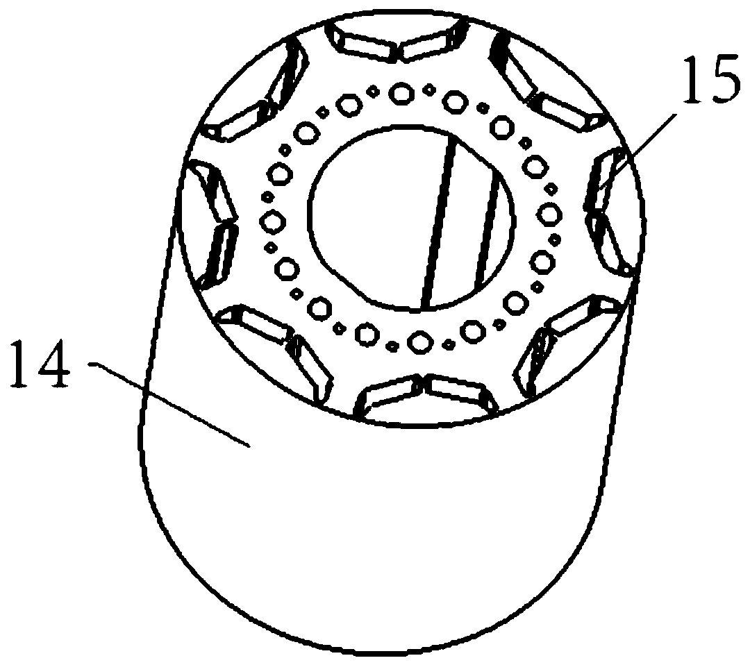
technical field [0001] The invention relates to a mechanism for assembling a rotor magnetic steel on a motor of a new energy vehicle. Background technique [0002] The rotor core 14 of the new energy motor rotor is as figure 1 As shown, there is a magnetic steel slot 15 on the rotor core 14 , and the magnetic steel needs to be assembled into the magnetic steel slot 15 . In the field of new energy motor rotor magnet assembly, there are many ways to assemble magnets. Whether it is unmagnetized magnets or pre-magnetized magnets, magnet feeding, shaping, retrieving, and inserting are required. step. Feeding includes vibrating plate feeding, magazine feeding, etc.; shaping includes swing cylinder shaping, material channel shaping, etc.; retrieving materials includes pneumatic truss retrieving, robot retrieving, etc. The insertion is basically the same, no matter what it is The method of retrieving materials must finally insert the magnetic steel into the magnetic steel slot, o...

Claims


Application Information

Patent Timeline
IPC IPC(8): B23P21/00B23P19/00H02K15/02H02K15/03
CPCB23P19/00B23P19/001B23P21/00H02K15/02H02K15/024H02K15/03
Inventor 李超王俊武张明欢
Owner COMAU SHANGHAI ENG
Learn More