Adjustable building reinforcement rust removing device

A construction steel bar, adjustable technology, applied in the direction of grinding drive device, grinding/polishing safety device, grinding machine parts, etc. The effect of ensuring the rust removal effect

Inactive Publication Date: 2020-01-07
时守东
View PDF9 Cites 2 Cited by
  • Summary
  • Abstract
  • Description
  • Claims
  • Application Information

AI Technical Summary

Problems solved by technology

[0003] Traditional derusting is done manually using tools, which is time-consuming and laborious. There are also some equipment that can replace manual derusting of steel bars. However, the working range of existing equipment is mostly not adjustable, and can only be used for derusting with a fixed length. certain inconvenience

Method used


Image

  • Adjustable building reinforcement rust removing device
  • Adjustable building reinforcement rust removing device
  • Adjustable building reinforcement rust removing device

Examples


Embodiment 1

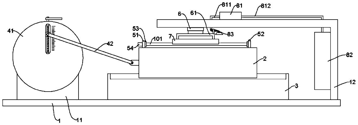
[0022] see Figure 1~4 , in the embodiment of the present invention, a kind of adjustable construction steel bar derusting device comprises base 1, and mounting frame 11, supporting base 3 and supporting frame 12 are fixed on base 1; The top of described supporting base 3 is slidingly connected with working Table 2, a clamping mechanism for fixing the steel bar 101 is arranged on the workbench 2; the lifting device 6 is installed on the position above the workbench 2 on the support frame 12, and the lifting device 6 is connected with the derusting disc 7 through the connecting frame 61 .

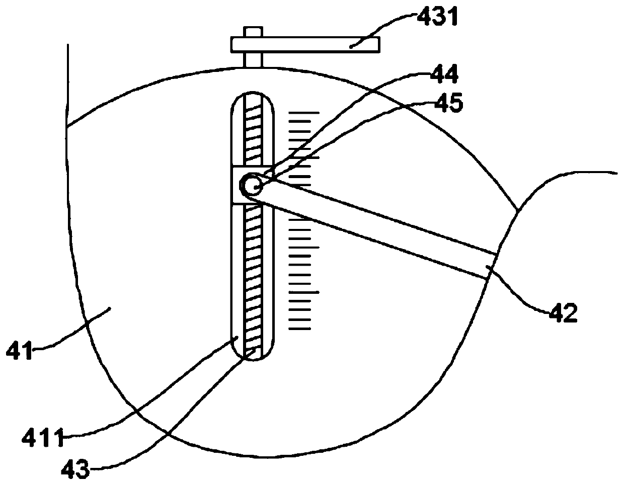
[0023] A driving mechanism for driving the workbench 2 to move is installed on the mounting frame 11; the driving mechanism includes a turntable 41, which is rotatably connected to the mounting frame 11 and driven by a motor (not shown in the figure). There is a chute 411 arranged along the radial direction, and the chute 411 is rotatably connected with a screw rod 43, and the outer periphe...

Embodiment 2

[0034] In this embodiment, an adjustable rust removal device for building steel bars also includes a dust removal mechanism; the dust removal mechanism includes a dust suction fan 81 and a purification box 82; the dust suction fan 81 and the purification box 82 are installed on the support 12, the input end and the output end of the dust suction fan 81 are respectively connected with a suction pipe 811 and an air outlet pipe 812, and the end of the suction pipe 811 extends to the top of the rust removal plate 7 and is connected with a dust suction head 83 for dust suction. The head 83 is fixed on the connecting frame 61; the cleaning liquid is filled in the cleaning box 82, and the end of the air outlet pipe 812 extends below the liquid level of the cleaning box 82; The impurities are sucked into the purification box 82, and the impurities are filtered by the purification liquid, which plays a role in protecting the environment.

[0035] Further, a filter screen 84 is provided...


PUM


Abstract

The invention discloses an adjustable building reinforcement rust removing device, and relates to the field of building trades. The device comprises a base; a mounting frame, a support base and a support frame are fixed on the base; a driving mechanism for driving a worktable to move is mounted on the mounting frame; the driving mechanism comprises a rotating disc; the rotating disc is provided with a chute formed in the radius direction; a lead screw is rotationally connected into the chute; a slide block in threaded fit with the lead screw sleeves the outer periphery of the lead screw; the slide block is clamped in the chute; one end of the lead screw extends out of the chute, and is connected with an operation handle; a connecting column is fixed on the slide block; a connecting rod sleeves the outer periphery of the connecting column; one end of the connecting rod is rotationally connected with the connecting column; and the other end of the connecting rod is hinged to the worktable. The rotating disc is provided with the slide block capable of moving in the radius direction, and the connecting column is fixed on the slide block, so that the rotating radius of the connecting column can be adjusted to finish adjustment of the working range, and the overall device generality is improved.

Description

technical field [0001] The invention relates to the field of construction industry, in particular to an adjustable derusting device for building steel bars. Background technique [0002] Rebar is the main material used in the construction industry for structural steel skeletons, and its cross-section is usually circular. When the steel bars are put into use, it is required that the surface should not be corroded, and since most of the steel bars are purchased in batches during construction, it is easy to cause some steel bars to rust due to the long storage time, and the rust removal treatment is required for this part of the steel bars before use. . [0003] Traditional derusting is done manually using tools, which is time-consuming and laborious. There are also some equipment that can replace manual derusting of steel bars. However, the working range of existing equipment is mostly not adjustable, and can only be used for derusting with a fixed length. A certain inconven...

Claims


Application Information

Patent Timeline
Patent Type & Authority Applications(China)
IPC IPC(8): B24B27/033B24B41/02B24B41/04B24B41/00B24B41/06B24B47/12B24B55/06
CPCB24B27/033B24B41/007B24B41/02B24B41/04B24B41/06B24B47/12B24B55/06
Inventor 时守东
Owner 时守东
Why Eureka
Try Eureka