Electromagnetically driven parallel clamping device and control system thereof

A technology of electromagnetic drive and electromagnetic drive, which is applied in the field of manipulators, can solve problems such as reducing the use effect, large installation space, and lagging response speed, and achieve the effects of prolonging service life, improving safety, and increasing clamping force

Pending Publication Date: 2020-01-07
GUANGZHOU WAYTOP ELECTRONICS
View PDF0 Cites 2 Cited by
  • Summary
  • Abstract
  • Description
  • Claims
  • Application Information

AI Technical Summary

Problems solved by technology

Pneumatic or hydraulically driven manipulators require a working medium for their movement, requiring a larger air pump or hydraulic pump, resulting in a larger installation space; due to the compressibility of gas, the movement speed of the cylinder is susceptible to load changes. and change; due to the high pressure of the working medium of pneumatic and hydraulic pressure, rubber parts are needed to realize the seal, and its service life will be invalid or reduce the use effect due to the wear of rubber parts; because there is a fluid in the process of pneumatic or hydraulic pressure During the filling process, the response speed will have a relatively large hysteresis effect; since the pneumatic or hydraulic control process requires a solenoid valve to be used together, the service life and response speed of the solenoid valve will also seriously restrict the application of pneumatic or hydraulic fingers

Method used


Image

  • Electromagnetically driven parallel clamping device and control system thereof
  • Electromagnetically driven parallel clamping device and control system thereof
  • Electromagnetically driven parallel clamping device and control system thereof

Examples


Embodiment 1

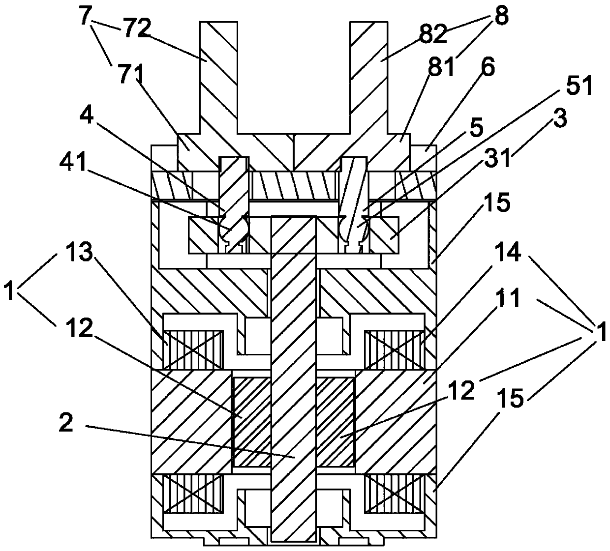
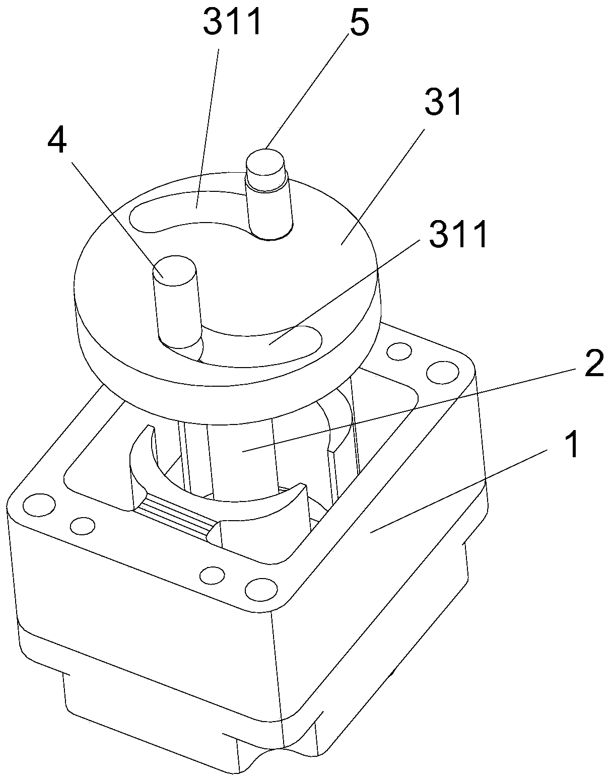
[0054] Such as figure 1 , figure 2 , Figure 4 , Figure 5 As shown, an electromagnetically driven parallel clamping device includes: a shaft rotating electromagnetic driver 1, a rotating shaft 2, a double transmission shaft retracting mechanism 3, a first transmission shaft 4, a second transmission shaft 5, a linear guide rail 6, a first clamping finger 7 and second clamping finger 8;

[0055] One end of the rotating shaft 2 is installed in the shaft rotating electromagnetic driver 1; the other end of the rotating shaft 2 extends out of the shaft rotating electromagnetic driver 1; the double transmission shaft retracting mechanism 3 is arranged on the rotating shaft 2 above, the rotating shaft 2 is fixedly connected to the middle part of the bottom surface of the double transmission shaft retracting mechanism 3; one end of the first transmission shaft 4 is connected to one side of the double transmission shaft retracting mechanism 3 and is arranged on the Above one side ...

Embodiment 2

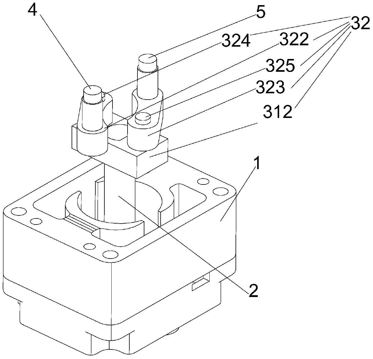
[0082] Such as image 3 , Figure 4 , Figure 5 As shown, an electromagnetically driven parallel clamping device includes: a shaft rotating electromagnetic driver 1, a rotating shaft 2, a double transmission shaft retracting mechanism 3, a first transmission shaft 4, a second transmission shaft 5, a linear guide rail 6, a first clamping finger 7 and second clamping finger 8;

[0083]One end of the rotating shaft 2 is installed in the shaft rotating electromagnetic driver 1; the other end of the rotating shaft 2 extends out of the shaft rotating electromagnetic driver 1; the double transmission shaft retracting mechanism 3 is arranged on the rotating shaft 2 above, the rotating shaft 2 is fixedly connected to the middle part of the bottom surface of the double transmission shaft retracting mechanism 3; one end of the first transmission shaft 4 is connected to one side of the double transmission shaft retracting mechanism 3 and is arranged on the Above one side of the double ...


PUM


Abstract

The invention particularly discloses an electromagnetically driven parallel clamping device which comprises a shaft rotating electromagnetic actuator, a rotating shaft, a dual transmission shaft retracting and expanding mechanism, a first transmission shaft, a second transmission shaft, a linear guide rail, a first clamping finger and a second clamping finger, wherein one end part of the rotatingshaft is mounted in the shaft rotating electromagnetic actuator; the other end of the rotating shaft extends out of the shaft rotating electromagnetic actuator; the rotating shaft is fixedly connectedwith the middle part of the bottom surface of the dual transmission shaft retracting and expanding mechanism; one end of the first transmission shaft is connected with one side part of the dual transmission shaft retracting and expanding mechanism; one end of the second transmission shaft is connected with the other side part of the dual transmission shaft retracting and expanding mechanism; oneend part of the first clamping finger is fixedly connected with the other end of the first transmission shaft; and one end part of the second clamping finger is fixedly connected with the other end ofthe second transmission shaft. The invention further discloses a control system for electromagnetically driven parallel clamping device. The electromagnetically driven parallel clamping device and the control system overcome the defect of pneumatic or hydraulic manipulators, and have the advantage of high control performance.

Description

technical field [0001] The invention relates to the technical field of manipulators, in particular to an electromagnetically driven parallel clamping device and a control system thereof. Background technique [0002] The continuous development of modern science and technology has greatly promoted the intersection and penetration of different disciplines, leading to technological revolution and transformation in the engineering field. The manipulator is a new technology emerging in the field of modern automatic control, and has become an important part of the modern mechanical manufacturing production system. This new technology develops rapidly and gradually forms a new discipline of manipulator engineering. The manipulator appeared in the late 1950s and has only developed rapidly in recent years. It has become an important equipment for industrial automation. The indispensable part of the manipulator is its fingers for gripping objects. At present, with the development of...

Claims


Application Information

Patent Timeline
Patent Type & Authority Applications(China)
IPC IPC(8): B25J15/02
CPCB25J15/0246B25J15/0253
Inventor 陈晓鸣
Owner GUANGZHOU WAYTOP ELECTRONICS
Why Eureka
Try Eureka