Machine arm structure of bridge erecting machine

A technology of a bridge erecting machine and an arm is applied in the application field of a bridge erecting machine, which can solve the problems of high energy consumption, large limitation and high cost, and achieve the effects of saving energy consumption, reducing weight and reducing weight.

Pending Publication Date: 2020-01-07
HEFEI ZHENGHAO MECHANICAL TECH
View PDF0 Cites 1 Cited by
  • Summary
  • Abstract
  • Description
  • Claims
  • Application Information

AI Technical Summary

Problems solved by technology

[0004] The purpose of the present invention is to provide a machine arm structure of a bridge erecting machine, which can solve the problem that although the existing bridge erecting machine arms have a variety of structural designs, their own weight in use is relatively large, and energy consumption during movement is large. , the cost of production and manufacturing is high, and the limitations are relatively large

Method used


Image

  • Machine arm structure of bridge erecting machine
  • Machine arm structure of bridge erecting machine
  • Machine arm structure of bridge erecting machine

Examples


Embodiment Construction

[0028] The technical solutions of the present invention will be clearly and completely described below in conjunction with the embodiments. Apparently, the described embodiments are only some of the embodiments of the present invention, not all of them. Based on the embodiments of the present invention, all other embodiments obtained by persons of ordinary skill in the art without creative efforts fall within the protection scope of the present invention.

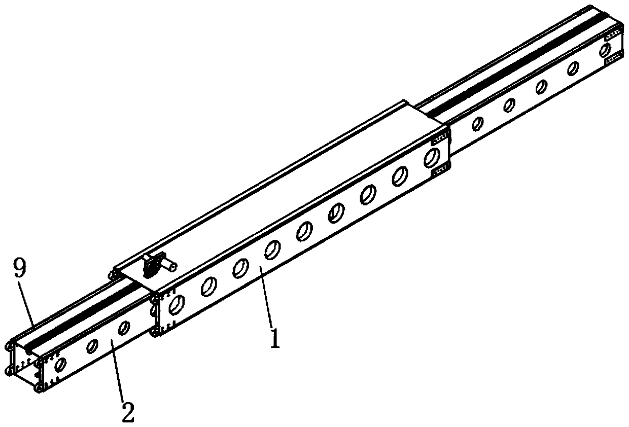
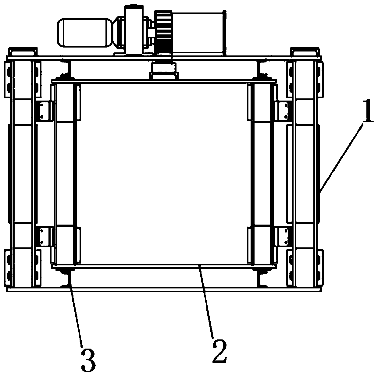
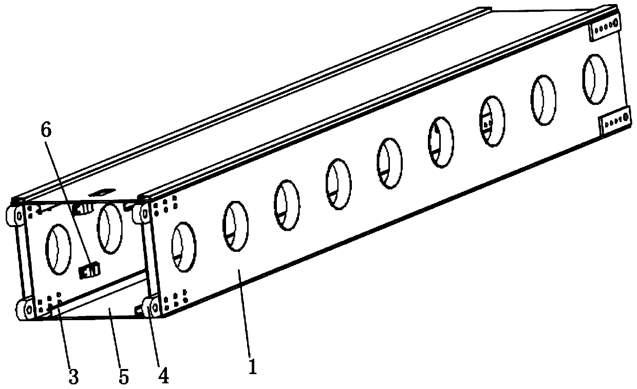
[0029] see Figure 1-6 As shown, an arm structure of a bridge erecting machine includes a main girder 1 and an inner guide beam 2, the inner guide girder 2 is slidably fitted inside the main girder 1, and both the inner guide girder 2 and the main girder 1 are box girders ;

[0030] The upper and lower ends of the inner guide beam 2 and the main beam 1 all include cover plates 10, the two sides of the upper and lower cover plates 10 are connected with the outer vertical plates 8, and the inner sides of the upper and lower ...


PUM


Abstract

The invention discloses a machine arm structure of a bridge erecting machine. The structure comprises a main beam and an inner guide beam, wherein the inner guide beam is arranged in the main beam ina sliding and sleeving manner, and the inner guide beam and the main beam are all box beams; and the upper end and the lower end of the inner guide beam and the upper end and the lower end of the mainbeam are provided with cover plates, the two sides of the upper and lower cover plates are connected with outer vertical plates, and the two sides of the interiors of the upper and lower cover platesare connected with inner vertical plates. According to the structure, the main beam and the inner guide beam adopt hollow arrangement of double vertical plates, so that during work, the anti-pressureability is good, and the weight can be reduced; on the premise that the rigidity and intensity of the machine arm is guaranteed, the constraint of the aspect ratio of the beams is eliminated to a certain extent; the overall demands of light weight and miniaturization of the bridge erecting machine are met, and the special requirements of the bridge erecting machine on the appearance size can be met; the overall weight of the bridge erecting machine is small during use, the energy consumption can be saved during movement, and the use cost and the manufacturing cost are reduced; and the size and the aspect ratio of the main beam do not need to be increased, and the bearing strength of the main beam with the same size can be achieved.

Description

technical field [0001] The invention relates to a machine arm structure, in particular to a machine arm structure of a bridge erecting machine, which belongs to the application field of bridge erecting machines. Background technique [0002] The machine arm is the load-bearing main girder of the bridge erecting machine. According to the force condition of the machine arm and finite element analysis and calculation, each main girder is designed as a box-shaped girder structure, or the main girder adopts a triangular truss structure, and the guide girder adopts a truss The structure design reduces weight and ensures sufficient rigidity. [0003] But the machine arm of existing bridge erecting machine still has certain deficiency in use. Although the existing bridge-erecting machine arms have multiple structural designs, they are heavy in use, consume a lot of energy during movement, have high production and manufacturing costs, and have relatively large limitations. At the s...

Claims


Application Information

Patent Timeline
Patent Type & Authority Applications(China)
IPC IPC(8): E01D21/00
CPCE01D21/00
Inventor 郑之松
Owner HEFEI ZHENGHAO MECHANICAL TECH
Why Eureka
Try Eureka