Steel wire knotting device for building construction and steel wire knotting method for construction

A steel wire knotting and building construction technology, which is applied in the processing of building materials, construction, building construction, etc., can solve problems such as forearm pain, low binding efficiency, and high labor intensity

Inactive Publication Date: 2020-01-07
马桂花
View PDF0 Cites 0 Cited by
  • Summary
  • Abstract
  • Description
  • Claims
  • Application Information

AI Technical Summary

Problems solved by technology

If the binding between the steel bars in the frame structure is manually bound, the binding efficiency is low. After working for a long time, the forearm will be severely sore, and the labor intensity of the workers will be high.
[0003] Now there are various automatic steel bar binding machines on the market, which greatly improves the efficiency of binding; greatly shortens the binding time and reduces labor costs; but the current steel bar binding machines often need two hands to operate at the same time, and the steel wire When bypassing the lower side of the steel bar, it needs to be completed manually. Only the tightening of the steel wire is completed by a binding machine, and the actual operation is more troublesome, so most of them still use manual binding at present. The invention designs a reasonable structure, convenient operation, A rebar binding machine that is able to operate with one hand and route the wire from the underside of the rebar without human involvement is essential when tying

Method used


Image

  • Steel wire knotting device for building construction and steel wire knotting method for construction
  • Steel wire knotting device for building construction and steel wire knotting method for construction
  • Steel wire knotting device for building construction and steel wire knotting method for construction

Examples


Embodiment Construction

[0041] The specific implementation manners of the present invention will be further described in detail below in conjunction with the accompanying drawings and embodiments. The following examples or drawings are used to illustrate the present invention, but not to limit the scope of the present invention.

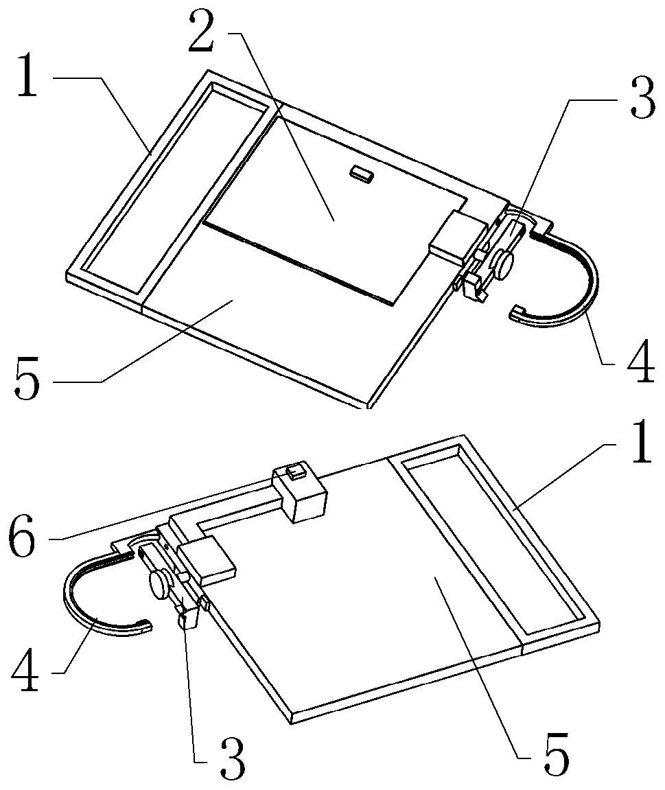
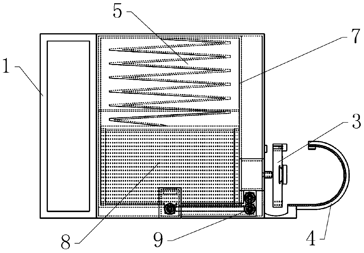
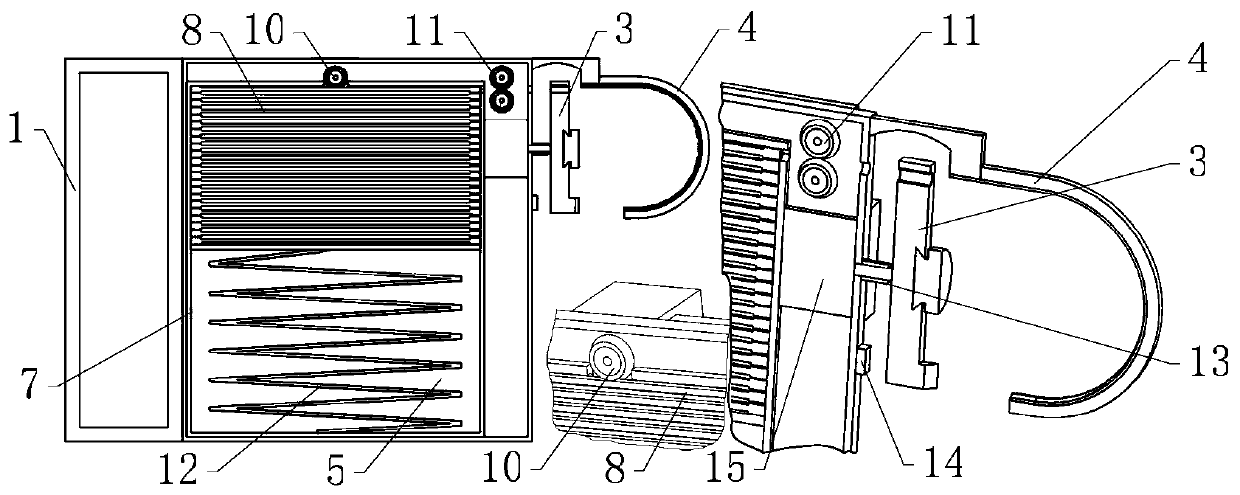
[0042] Such as figure 1 As shown, it includes a binding drive bar 3, a delivery guide rail 4, a housing 5, and a wire delivery mechanism 9, wherein as figure 2 , 3 , 8, the housing 5 is equipped with a steel wire card frame 7 for holding the steel wire 8; the delivery push plate 26 for pushing the steel wire 8 is installed in the steel wire card frame 7 by sliding fit, and the back side of the delivery push plate 26 is in contact with the steel wire card frame 7. A sheet-shaped compression spring 12 is installed between the corresponding end faces of the steel wire frame 7; Figure 4 As shown, the housing 5 is provided with a clamping steel wire opening 16, and a door 2...


PUM


Abstract

The invention belongs to the technical field of steel wire knotting and especially relates to a steel wire knotting device for building construction. The device comprises a binding driving bar, a conveying guiderail, a shell and a steel wire conveying mechanism. During binding of reinforcing steel bars, the conveying guiderail is at first hooked between the two reinforcing steel bars to be bound,so a turntable installed on the binding driving bar can be pressed on the two reinforcing steel bars; then, a binding mechanism is moved upwards for a short distance, a driving motor is switched on bya switch button and starts work, a steel wire clamped in advance inside the shell is conveyed out by the steel wire conveying mechanism, and a speed reduction stepping motor starts work when a secondsteel wire thickening end on the steel wire gets contact with a sensor on the shell; and the binding driving bar is driven by the speed reduction stepping motor to rotate and wind the steel wire. Incomparison with traditional manual binding, the device disclosed by the invention has the beneficial effects that binding efficiency is high and workers' labor strength is low; and in comparison withexisting binding machines of reinforcing steel bars, the device can be operated conveniently and can be operated with one hand.

Description

technical field [0001] The invention belongs to the technical field of steel wire knotting, and in particular relates to a steel wire knotting device for building construction and a steel wire knotting method for building construction. Background technique [0002] In modern society, infrastructure is essential to the country. During construction projects, steel bars are usually bound into a frame and then poured with cement to form reinforced concrete. Its toughness and firmness are good, so it can be developed on a large scale. If the binding between the steel bars in the frame structure is manually bound, the binding efficiency is low. After working for a long time, the forearm will be severely sore, and the labor intensity of the worker is relatively high. [0003] Now there are various automatic steel bar binding machines on the market, which greatly improves the efficiency of binding; greatly shortens the binding time and reduces labor costs; but the current steel bar ...

Claims


Application Information

Patent Timeline
Patent Type & Authority Applications(China)
IPC IPC(8): E04G21/12
CPCE04G21/123
Inventor 马桂花
Owner 马桂花
Why Eureka
Try Eureka