Blade for centrifugal fan impeller, centrifugal fan impeller and extractor hood

A centrifugal fan and impeller technology, which is applied to the components of the pumping device for elastic fluid, the removal of oil fume, the machine/engine, etc., can solve the problem of increasing the viscous resistance near the impeller wall, aggravating the airflow collision loss, and easily causing end face separation. vortex and other problems, to achieve the effect of not weakening the working ability, suppressing disturbance, and increasing the distance

Active Publication Date: 2020-01-07
NINGBO FOTILE KITCHEN WARE CO LTD
View PDF10 Cites 5 Cited by
  • Summary
  • Abstract
  • Description
  • Claims
  • Application Information

AI Technical Summary

Problems solved by technology

[0004] But the defect that this impeller exists is: 1, the airflow of centrifugal fan exists the process that turns from axial direction to radial direction, and there is certain angle of attack when airflow enters flow passage, and the outlet end and the inlet section of the blade of this impeller are all designed It is wavy, and this structure will increase the collision loss of the airflow at the blade inlet and increase the aerodynamic noise of the impeller; 2. Along the length of the blade, the edge of the blade is wavy, and the blade is close to the front ring and the back ring. It is designed to be wave-shaped and basically cannot play the role of noise reduction, and this will lead to relatively dispersed outlet airflow, which is more likely to generate end-face separation vortices, which will increase the viscous resistance near the wall when the impeller rotates, which is obviously unfavorable

Method used


Image

  • Blade for centrifugal fan impeller, centrifugal fan impeller and extractor hood
  • Blade for centrifugal fan impeller, centrifugal fan impeller and extractor hood
  • Blade for centrifugal fan impeller, centrifugal fan impeller and extractor hood

Examples


Embodiment Construction

[0029] The present invention will be further described in detail below in conjunction with the accompanying drawings and embodiments.

[0030] Such as Figure 1~4 As shown, the range hood of this preferred embodiment includes a casing and a centrifugal fan arranged in the casing, and the centrifugal fan includes a motor and a centrifugal fan impeller connected to the output shaft of the motor. In this embodiment, the centrifugal fan impeller includes A front ring 3 , a rear ring 4 opposite to the front ring 3 , a wheel disc 5 and at least two blades A.

[0031] Such as Figure 4 As shown, the wheel disc 5 is located between the front ring 3 and the rear ring 4, and the edge of the wheel disc 5 is connected with the rear ring 4 through at least two strip-like webs 51. Fixed perforation 52 .

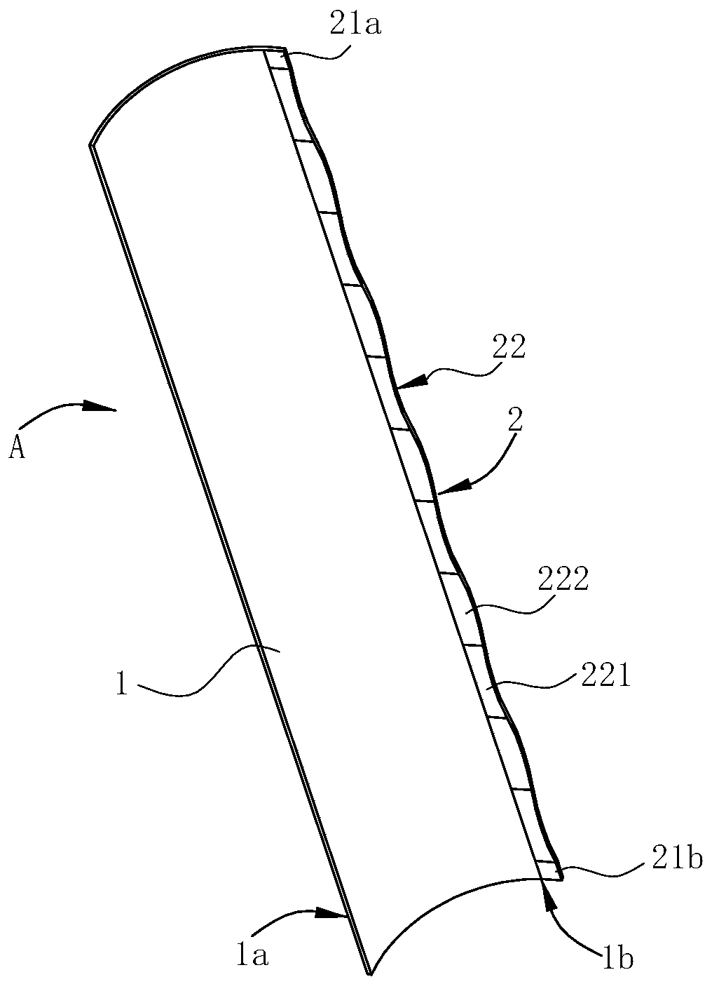
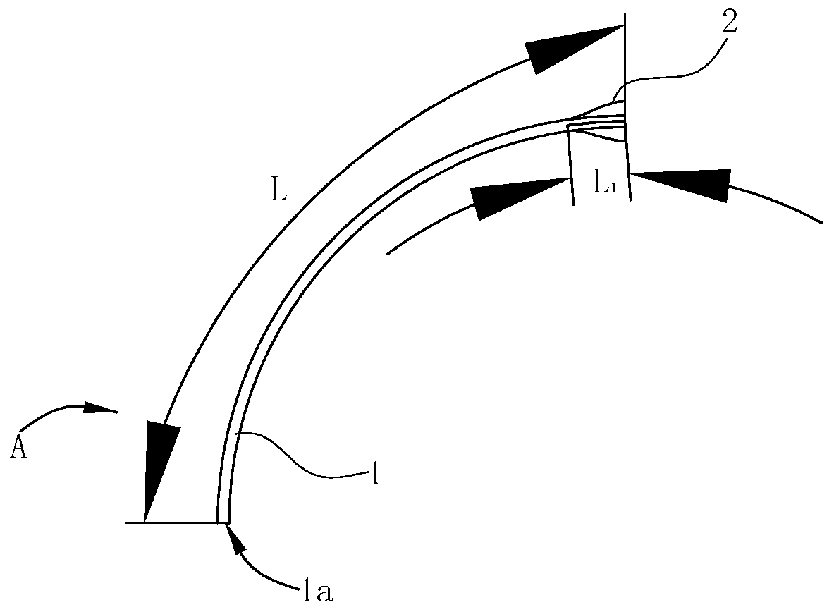
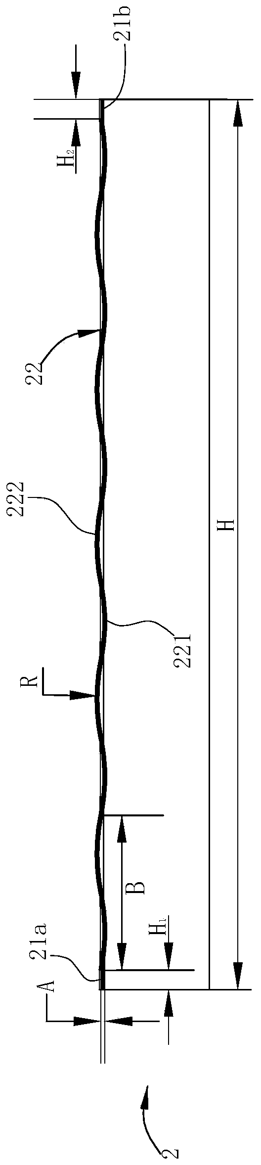
[0032] A plurality of blades A are arranged at intervals along the circumferential direction of the front ring 3, and the two ends of each blade A are respectively fixed on the front ri...


PUM


Abstract

The invention relates to a blade for a centrifugal fan impeller, the centrifugal fan impeller and an extractor hood. The blade for the centrifugal fan impeller includes a blade body, a first side edgeand a second side edge are arranged on the blade body side by side in the length direction and in an extension mode, wherein the first side edge is an inlet edge corresponding to airflow inflow, thesecond side edge is an outlet edge corresponding to airflow outflow, the blade body is characterized in that a noise reduction part capable of reducing noise is only arranged at the outlet edge, the noise reduction part is strip-shaped and extends in the length direction of the blade body, the noise reduction part includes two straight segments and a curve segment located between the two straightsegments, and the longitudinal section of the curve segment in the length direction of the curve segment is wave-shaped. According to the blade for the centrifugal fan impeller, the noise reduction part is only arranged at the outlet edge of the blade body, compared with the structure which noise reduction parts are arranged at the outlet edge and the inlet edge, the collision loss of an airflow at a blade inlet cannot be aggravated, and thus aerodynamic noise of the impeller cannot be increased.

Description

technical field [0001] The invention belongs to the technical field of centrifugal fans, and in particular relates to a blade for a centrifugal fan impeller, a centrifugal fan impeller and a range hood. Background technique [0002] The centrifugal fan is widely used, and the impeller is an important component of the centrifugal fan. The rotation of the impeller drives the gas flow, and whether its structure is reasonable directly affects the overall performance of the fan. When the range hood is working, the motor is directly connected to drive the impeller to rotate, and the oil fume sucked in the axial direction is thrown out of the impeller radially from the center of the impeller under the action of centrifugal force. However, due to the large curvature of the blade, it is easy to form a reverse pressure gradient on the blade surface, causing the flow separation at the trailing edge of the suction surface, which not only disturbs the flow in the main flow area of ​​the ...

Claims


Application Information

Patent Timeline
Patent Type & Authority Applications(China)
IPC IPC(8): F04D29/30F04D29/28F04D29/66F24C15/20
CPCF04D29/283F04D29/30F04D29/663F04D29/666F04D29/667F24C15/20
Inventor 胡泽元孙佳琪李晓强茅忠群诸永定
Owner NINGBO FOTILE KITCHEN WARE CO LTD
Why Eureka
Try Eureka