Low-pollution combustion chamber and combustion control method thereof

A combustion chamber, low-polluting technology, applied in combustion methods, combustion chambers, continuous combustion chambers, etc., can solve problems such as poor fuel atomization, good premixing and preevaporation, and strong air swirl effect.

Active Publication Date: 2020-01-07
AECC COMML AIRCRAFT ENGINE CO LTD
View PDF5 Cites 10 Cited by
  • Summary
  • Abstract
  • Description
  • Claims
  • Application Information

AI Technical Summary

Problems solved by technology

Under different engine working conditions, due to the change of the intake air volume of the swirler and the change of the turbulence intensity of the swirling air, the degree of premixing and pre-evaporation may be inconsistent in different working conditions, resulting in the flashback of the main combustion stage (large working condition In this case, the fuel injection momentum is high, the fuel initial atomization is good, the air swirl effect is strong, and the degree of premixing and pre-evaporation is too good), or there are large particles of unevaporated fuel at the outlet of the main combustion stage (smaller working conditions, The fuel injection momentum is small, the air turbulence intensity is weak, the fuel atomization is poor, the degree of premixing and pre-evaporation is too poor), the equivalence ratio is uneven, resulting in a decrease in combustion efficiency, hot spots in the combustion zone, and increased NOx emissions at the outlet of the combustion chamber And other issues

Method used

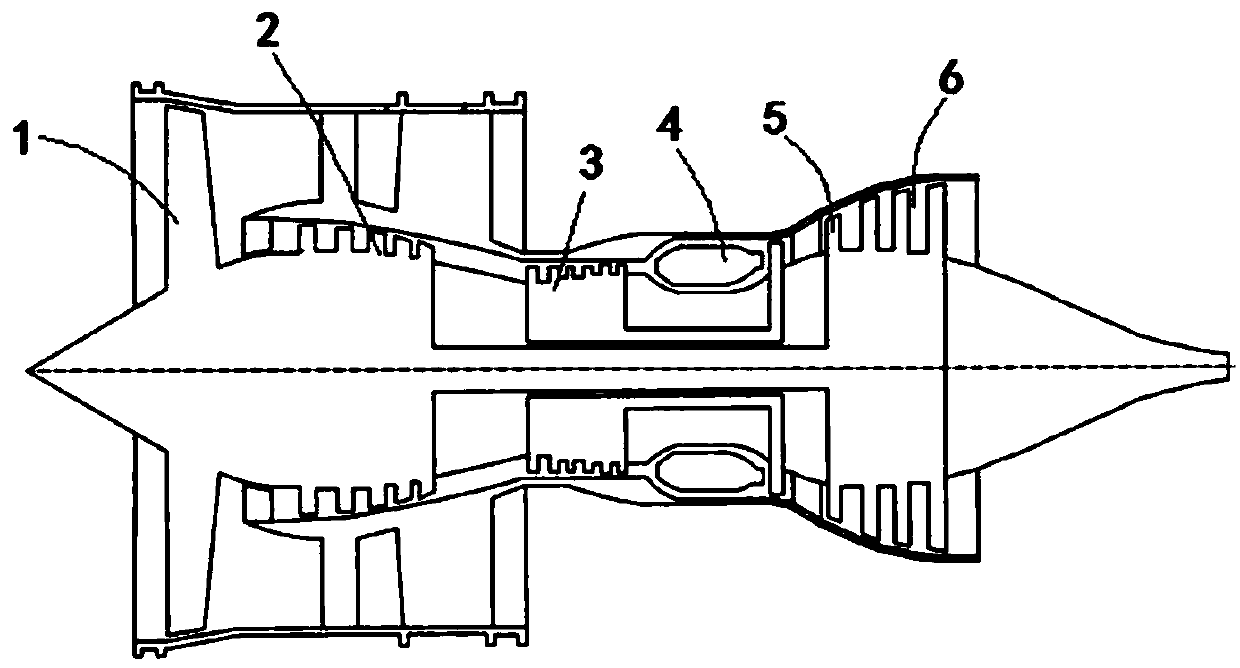
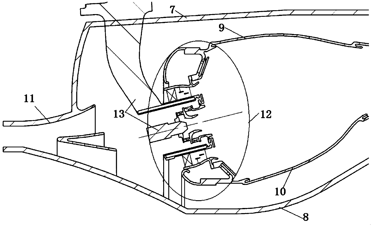
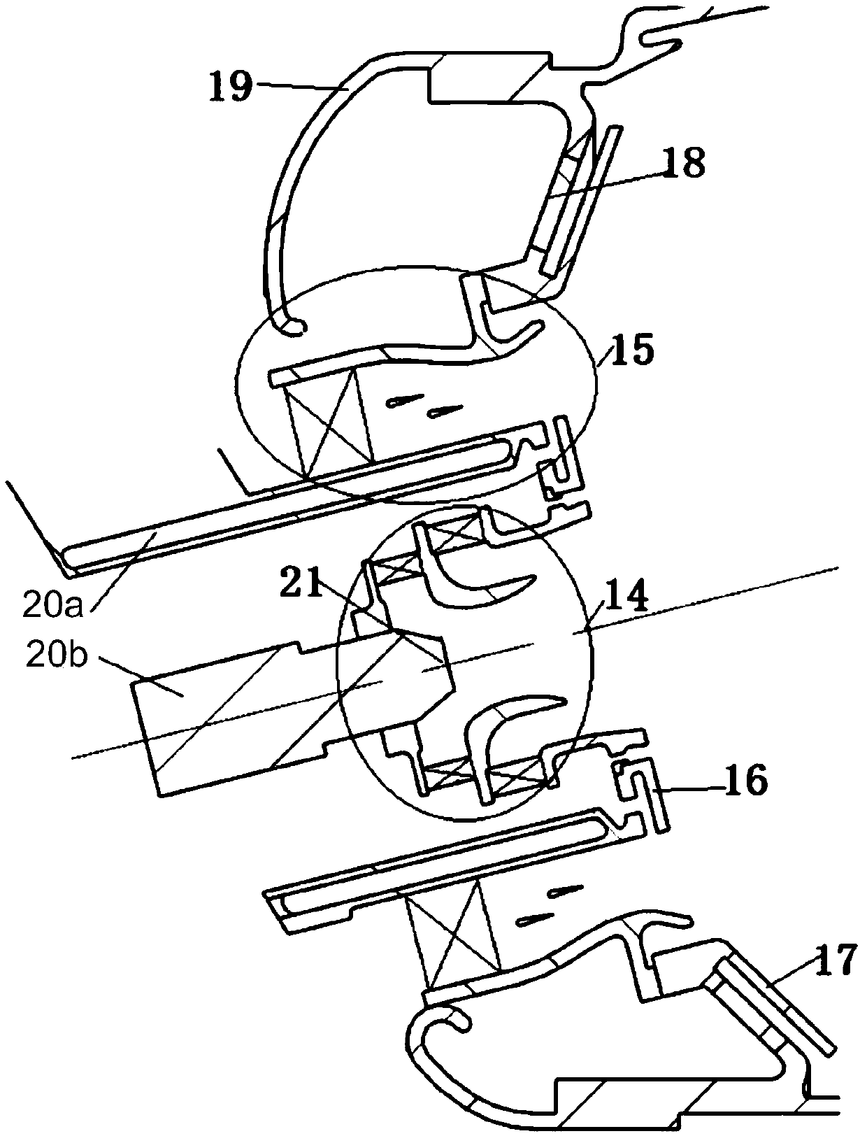

Image

  • Low-pollution combustion chamber and combustion control method thereof
  • Low-pollution combustion chamber and combustion control method thereof
  • Low-pollution combustion chamber and combustion control method thereof

Examples


Embodiment Construction

[0026] A variety of different implementations or examples for implementing the described subject technical solutions are disclosed below. In order to simplify the disclosure, the following describes the specific examples of each component and arrangement, of course, these are only examples, not limiting the protection scope of the present invention. For example, the description that the first feature described later in the description is formed on or above the second feature may include an embodiment in which the first and second features are formed through direct contact, and may also include an embodiment in which the first and second features are formed between the first and second features. Embodiments of additional features such that there may be no direct relationship between the first and second features. Additionally, reference numerals and / or letters may be repeated in different instances in these disclosures. This repetition is for brevity and clarity and does not i...


PUM


Abstract

The invention relates to a low-pollution combustion chamber and a combustion control method thereof. The low-pollution combustion chamber comprise a combustion chamber head, the combustion chamber head comprises a primary combustion stage and a pre-combustion stage, and the primary combustion stage comprises a primary combustion stage channel and a primary combustion stage swirler arranged in theprimary combustion stage channel. The low-pollution combustion chamber is characterized in that the primary combustion stage further comprises a pre-mold plate arranged in the primary combustion stagechannel, the pre-mold plate is divided into an outer-layer pre-mold plate and an inner-layer pre-mold plate in the radial direction, wherein the spraying point position and the spraying direction offuel oil of the primary combustion stage are arranged to control the primary combustion stage fuel oil to be sprayed into the primary combustion stage channel through a primary combustion stage fuel oil spray hole, the primary combustion stage direct-injection oil mist is partially formed, and the other part of the the primary combustion stage fuel oil is sprayed on the pre-mold plate close to theinner side of the primary combustion stage channel or sprayed on the two layers of pre-mold plates. Through cooperation of the double-layer pre-mold plate and the spraying point position and the spraying direction, and the combustible mixed gas is distributed more uniformly in a flame tube under different working conditions.

Description

technical field [0001] The invention relates to an aviation gas turbine combustion chamber and a combustion control method. Background technique [0002] The main development trend of modern civil aeroengine combustors is low-pollution combustion. Combustion chambers of civil aeroengines must meet increasingly stringent aeroengine pollution emission standards. The currently adopted CAEP6 (Committee on Aviation Environmental Protection) standard has very strict regulations on pollutant emissions, especially for NOx pollution emission requirements; and the latest CAEP8 standard proposes to reduce NOx emissions by 15% on the CAEP6 emission standard, With the rapid development of the aviation industry and the continuous improvement of people's awareness of environmental protection, higher requirements will be put forward for the pollution emissions of gas turbine combustors in the future. In order to meet the increasingly stringent pollution emission standards, advanced low-po...

Claims


Application Information

Patent Timeline
Patent Type & Authority Applications(China)
IPC IPC(8): F23R3/28
CPCF23R3/28F23R3/16F23R3/286F23R3/343F23R3/14F23D2900/11101F23D2900/11001F23R3/30
Inventor 党龙飞何沛陈伟徐榕鄂亚佳陈盼苏明明陈浩
Owner AECC COMML AIRCRAFT ENGINE CO LTD
Why Eureka
Try Eureka