Electrosurgical snare

a technology of electrosurgical and snare, which is applied in the field of surgical snare, can solve the problems of high electrical power (in particular the use of high voltage), the risk of unwanted thermal damage to the bowel wall, etc., and achieve the effect of reducing the risk of collateral thermal damag

Active Publication Date: 2020-03-26
CREO MEDICAL LTD
View PDF0 Cites 0 Cited by
  • Summary
  • Abstract
  • Description
  • Claims
  • Application Information

AI Technical Summary

Benefits of technology

[0007]At its most general, the present invention proposes snare structures arranged to radiate microwave frequency energy (e.g. electromagnetic energy with a frequency of at least three orders of magnitude higher than typical RF energy) within the area encircled by the snare's loop. By controlling the shape of the emitted microwave field, the risk of collateral thermal damage can be reduced. For example, typical peak voltages in embodiments of the invention are 10 V or less. Moreover, the emitted microwave field can be more effective than an RF field at coagulating blood.
[0013]One advantage of using microwave frequency energy is that the depth of penetration of the electric field into biological tissue is small, e.g. of the order of millimetres at the frequency of choice. The focussed heat profile depends on the square of the electric field, and the conductivity, density and specific heat capacity of the target tissue being treated. The microwave field emitted by the radiating microwave monopole antenna is therefore naturally confined to biological tissue in the region of the snare, thereby reducing the risk of collateral thermal damage.
[0023]In one embodiment, the snare base comprises a terminal cap fixed to the distal end of the sleeve. The second end of the length of conductive material that forms the retractable loop may be attached to an outer surface of the coaxial cable. If the coaxial cable is slidable within the sleeve, this arrangement means that the second end of the retractable loop can be moved within the sleeve. This may facilitate full retraction of the snare.
[0024]The retractable loop may be made from any suitable wire-like material, e.g. nitinol, nylon, metal wire or the like. Preferably the material has shape retaining properties so that it automatically adopts a loop configuration upon being released from a retracted configuration. Thus, the retractable loop may comprise a wire that extends beyond the distal end of the coaxial cable, the wire being arranged to naturally adopt a looped shape between two ends located at the distal end of the coaxial cable. The retractable loop may be adjustable to vary the length of wire between the two ends. The looped shape may be free from irregularities. In particular, the looped shape may not require a distal hump or nib such as those commonly found on conventional surgical snares to ensure that they retract in a predetermined manner. The invention may obviate the need for such a nib through the use of nitinol as the loop material, and / or through the use of the deployment mechanisms set forth herein. Omitting the distal nib may ensure that the snare provides a cleaner mechanical cut, which in turn provides a better en-bloc specimen for histological assessment and facilitates complete excision of tissue circled by the snare.
[0030]The elongate conductive member may be retractable independently of the retractable loop. For example, the sleeve and the coaxial cable may be movable relative to other to move the elongate conductive member between a storage position in which it is surrounded by the elongate conductive member and a use position it which it protrudes from the sleeve. The retractable loop may be operable as a “cold” snare, i.e. a snare that operates without an accompanying microwave radiation field, when the elongate conductive member is in the storage position. In this arrangement, the snare may be used as a mechanically tissue capture and cutting tool. Tissue, e.g. a polyp stalk, may be encircled by the retractable loop when in an extended configuration. Upon retracting the loop, the encircled tissue may be forced against a distal surface of the snare base, whereupon the loop passes through the tissue to physically cut it. The distal surface of the snare base thus provides a reaction surface for the mechanical cutting action of the loop. The surface of the loop (or perhaps only the inner surface of the loop) may be roughened or sharpened to make this physical cutting action more effective. In some circumstances, use of the device as a “cold” snare may be preferable, as it may reduce the risk of delayed bleeding.
[0045]The coaxial cable or sleeve may provide a torque-stable cable capable of transferring a rotational movement effected at the proximal end of the device to the retractable loop. Rotation of the loop enables the snare to be easily position over and around a polyp. In this aspect, the outer jacket of the co-axial cable may be semi-rigid or a tube (catheter) may be inserted over the outer jacket and form a tight fit.

Problems solved by technology

A disadvantage of known RF cutting snares is the high level of electrical power (in particular the use of high voltages) needed to initiate cutting action, as it carries with it the risk of unwanted thermal damage to the bowel wall.

Method used


Image

  • Electrosurgical snare
  • Electrosurgical snare
  • Electrosurgical snare

Examples


Embodiment Construction

; FURTHER OPTIONS AND PREFERENCES

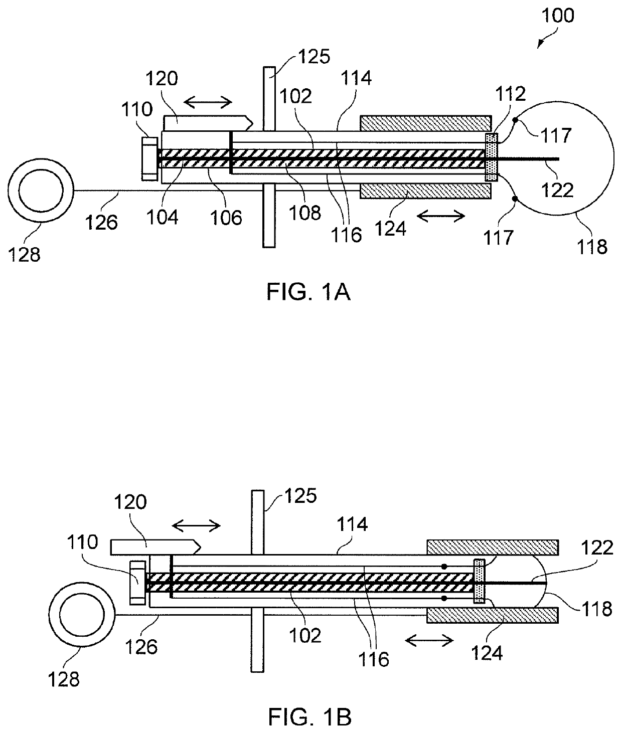
[0068]FIG. 1A shows a cross-sectional view through a surgical snare 100 that is an embodiment of the invention. The drawing is schematic and not to scale. In particular, the relative length of the device is shortened substantially. In practice, the largest width (diameter) of the device is less than 2.6 mm in order to make it suitable for passing through the instrument channel of an endoscope. The total length of the device, meanwhile, may be 2 m or more.

[0069]The surgical snare 100 comprises a coaxial cable 102, comprising an inner conductor 104, an outer conductor 106 and a dielectric material 108 separating the inner conductor 104 from the outer conductor 106. A microwave connector 110 (e.g. a QMA connector or the like) is mounted at a proximal end of the coaxial cable 102 for connecting to a microwave signal generator (not shown). A snare base 112 (e.g. a disc of a suitable insulator, e.g. a low loss microwave ceramic, PTFE, PEEK, Nylon or the li...


PUM


Abstract

An electrosurgical snare, e.g. suitably sized for insertion down the instrument channel of an endoscope, arranged to radiate microwave frequency energy (e.g. having a frequency greater than 1 GHz) from an elongate conductive element within an area encircled by a retractable loop. The elongate conductive element and retractable loop may be independently slidable relative to a snare base at a distal end of a sleeve to provide an appropriate device configuration. By controlling the shape of the emitted microwave field, the risk of collateral thermal damage can be reduced.

Description

CROSS-REFERENCE TO RELATED APPLICATION[0001]This application is a Divisional of U.S. patent application Ser. No. 14 / 904,417, filed Jan. 11, 2016, which is a National Stage entry of International Application No. PCT / GB2014 / 051957, filed Jun. 26, 2014, which claims priority to United Kingdom Patent Application No. 13124146.9, filed Jul. 11, 2013. The disclosures of the priority applications are incorporated in their entirety herein by reference.FIELD OF THE INVENTION[0002]The invention relates to a surgical snare, e.g. for use in a polypectomy procedure. In particular, the invention may be concerned with medical snares suitable for insertion down the instrument channel of an endoscope (or any other type of scoping device used in the gastrointestinal (GI) tract or elsewhere in the human or animal body), and which include a means for introducing electromagnetic energy into biological tissue.BACKGROUND TO THE INVENTION[0003]Polyps in the GI tract can be removed using a medical snare in a...

Claims


Application Information

Patent Timeline
Patent Type & Authority Applications(United States)
IPC IPC(8): A61B18/14A61B17/3205A61B18/18A61B17/221
CPCA61B2018/00607A61B2018/141A61B17/221A61B2017/2212A61B2018/00589A61B18/1402A61B2018/1861A61B18/1815A61B2018/144A61B2018/00875A61B2018/1853A61B2018/00494A61B17/32056A61B18/1482A61B18/1492A61B2018/1407
Inventor HANCOCK, CHRISTOPHER PAULWHITE, MALCOLMGULLIFORD, CRAIGSAUNDERS, BRIANHOLMES, SANDRA MAY BERNADETTE
Owner CREO MEDICAL LTD
Why Eureka
Try Eureka