Residual current detection device and residual current action protection system

A technology of residual current and detection device, applied in the direction of measurement device, circuit device, measurement current/voltage, etc., can solve the problem of single measurement range and so on

Active Publication Date: 2020-01-07
SHENZHEN POWER SUPPLY BUREAU
View PDF4 Cites 2 Cited by
  • Summary
  • Abstract
  • Description
  • Claims
  • Application Information

AI Technical Summary

Problems solved by technology

[0004] Based on this, it is necessary to provide a residual current detection device and a residual current action protection system for the problem that the traditional DC residual current detection method has a single measurement range.

Method used


Image

  • Residual current detection device and residual current action protection system
  • Residual current detection device and residual current action protection system
  • Residual current detection device and residual current action protection system

Examples


Embodiment Construction

[0068] In order to make the above-mentioned purpose, features and advantages of the present application more obvious and understandable, the specific implementation manners of the present application will be described in detail below in conjunction with the accompanying drawings. In the following description, numerous specific details are set forth in order to provide a thorough understanding of the application. However, the present application can be implemented in many other ways different from those described here, and those skilled in the art can make similar improvements without departing from the connotation of the present application. Therefore, the present application is not limited by the specific implementation disclosed below.

[0069] It should be noted that when an element is referred to as being “disposed on” another element, it may be directly on the other element or there may also be an intervening element. When an element is referred to as being "connected to"...


PUM


Abstract

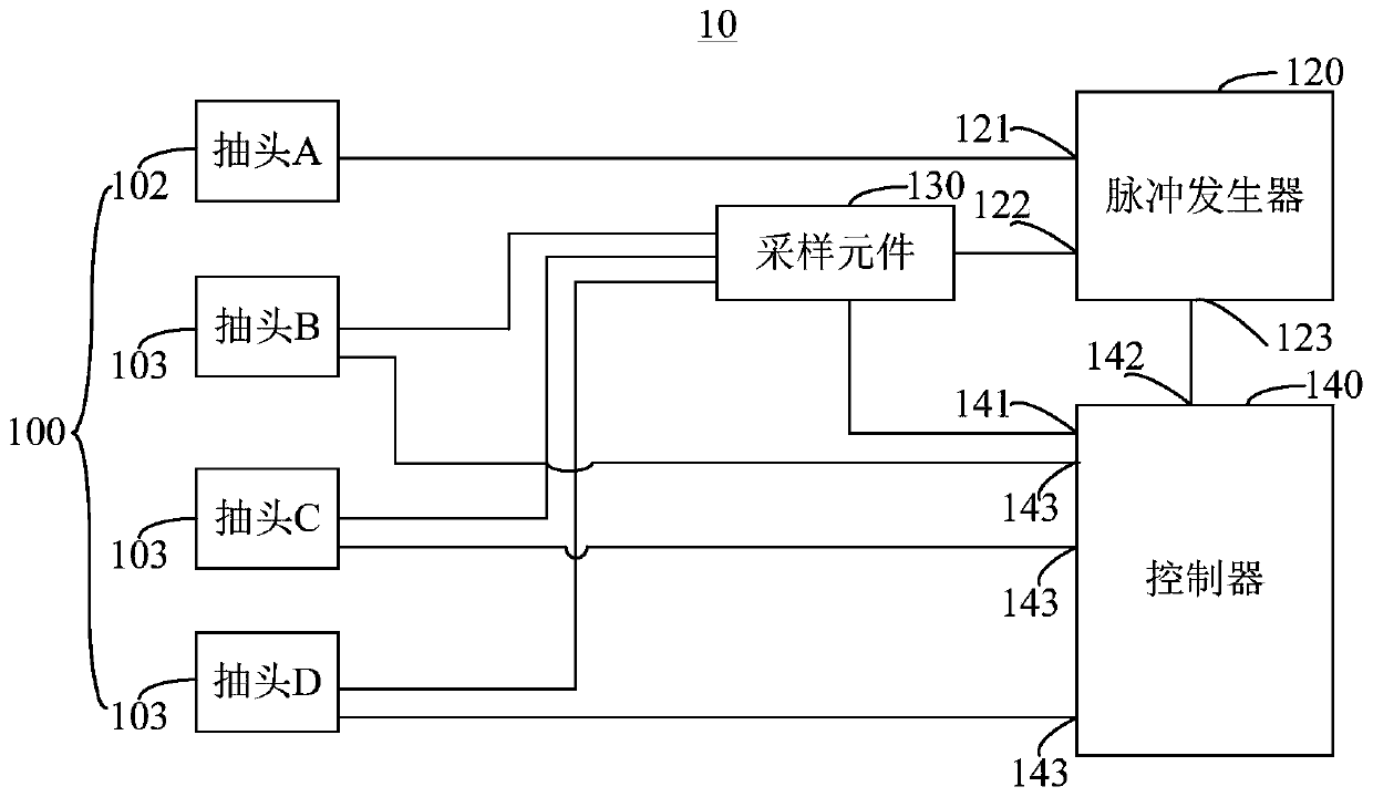
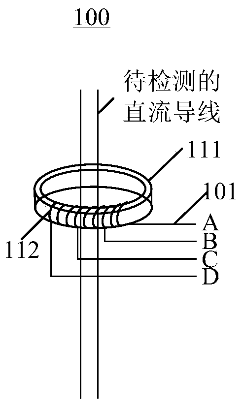
The invention relates to a residual current detection device and a residual current action protection system. The residual current detection device comprises a transformer, a pulse generator, a sampling element and a controller, wherein the transformer comprises a plurality of taps; the controller controls the pulse generator to transmit a pulse signal with a certain frequency and a certain amplitude to the transformer; the transformer induces residual current on a to-be-detected DC conductor under the action of the pulse signal; the controller obtains a true residual current value on the to-be-detected DC conductor through collecting voltage on the sampling element; and the controller selects the number of turns of a coil of the transformer through controlling on / off of the taps, therebychanging the range of the residual current detection device. The residual current detection device can change the range to achieve detection on wide-range residual current on the basis of high detection accuracy.

Description

technical field [0001] The present application relates to the technical field of electrical equipment, in particular to a residual current detection device and a residual current action protection system. Background technique [0002] Residual current is a major cause of electrical fires and personal electric shock accidents. There are many reasons for the remaining, such as the insulation aging of electrical equipment due to lack of effective maintenance, irregular distribution installation, overloading of distribution lines, and the insulation level of wires affected by the natural environment declines under wet conditions. At the same time, these reasons also lead to complex and diverse forms of residual current, which brings challenges to the design and development of residual current operated protectors. [0003] In the field of housing construction and municipal administration, due to various reasons for the generation of DC residual current, the range of DC residual ...

Claims


Application Information

Patent Timeline
IPC IPC(8): G01R1/28G01R31/00G01R15/18G01R19/00H02H3/32H02M9/02
CPCG01R1/28G01R31/00G01R15/183G01R19/00H02H3/32H02M11/00
Inventor 艾精文赵宇明王静陈思磊谢智敏
Owner SHENZHEN POWER SUPPLY BUREAU
Why Eureka
Try Eureka