
Power device for rectifier

A technology of power devices and rectifiers, which is applied in the direction of electric solid-state devices, semiconductor devices, semiconductor/solid-state device components, etc., can solve the problems of affecting the efficiency of rectifiers, the circuit is easy to be complicated, and the on-resistance becomes large, so as to reduce VF and conduction Low on-resistance and improved packaging reliability

Active Publication Date: 2020-01-07
ACTRON TECH
View PDF3 Cites 0 Cited by
  • Summary
  • Abstract
  • Description
  • Claims
  • Application Information

AI Technical Summary

Problems solved by technology

However, because the circuit system needs to be combined with control IC and other devices, the circuit between the devices is easy to be complicated and the on-resistance becomes larger, which affects the efficiency of the rectifier

Method used


Image

  • Power device for rectifier
  • Power device for rectifier
  • Power device for rectifier

Examples


Embodiment Construction

[0062] Exemplary embodiments of the present invention will be fully described below with reference to the accompanying drawings, but the invention may also be embodied in many different forms and should not be construed as being limited to the embodiments described herein. In the drawings, for the sake of clarity, the sizes and thicknesses of regions, parts and layers may not be drawn in actual scale. For the convenience of understanding, the same components in the following description will be described with the same symbols.

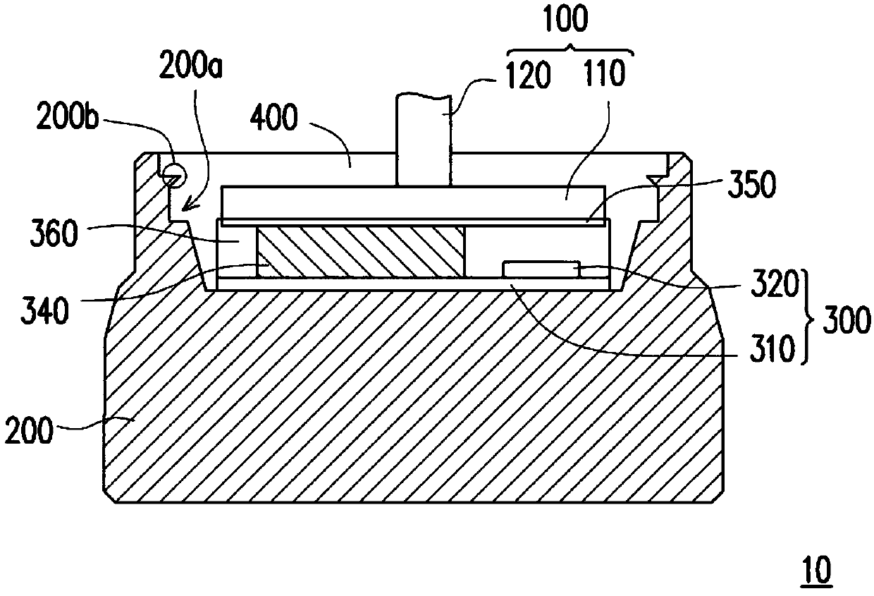
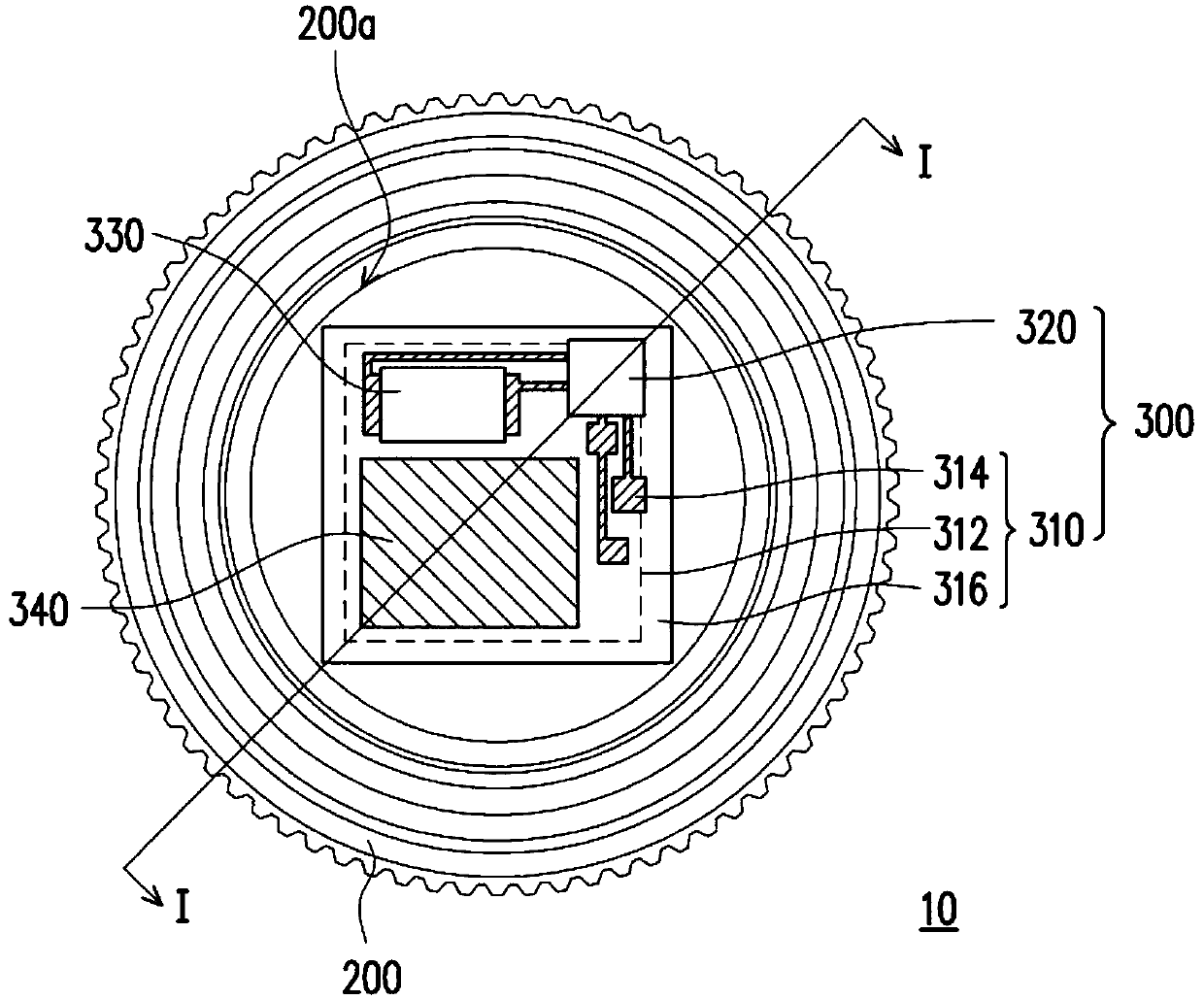
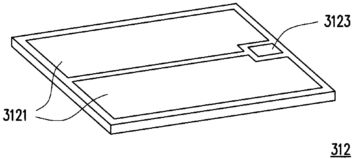
[0063] figure 1 is a schematic cross-sectional view of a power device according to an embodiment of the present invention. figure 2 yes figure 1 top view diagram. For clarity, in figure 2 Some components of the power device are omitted in the figure. Figure 3A and Figure 3B It is a front and back schematic view of a preformed transistor chip according to an embodiment of the present invention.

[0064] Please also refer to Figure 1 to Figu...


PUM


Abstract

The invention provides a power device for a rectifier. The power device comprises a first terminal, a second terminal and a circuit system, wherein the first terminal and the second terminal are usedfor connecting an external circuit, and the circuit system is located between the first terminal and the second terminal. The circuit system is electrically connected with the first terminal and the second terminal. The circuit system includes a pre-formed transistor chip and a control device. The pre-formed transistor chip includes a transistor having a first electrode, a second electrode and a third electrode, and a first package for packaging the transistor. The first terminal, the second terminal and the control device are electrically connected to the first electrode, the second electrodeand the third electrode of the transistor respectively.

Description

technical field [0001] The invention relates to a power device, in particular to a power device for a rectifier. Background technique [0002] In the existing automobile transportation system, since the efficiency and lifespan of the alternator are much higher than that of the DC generator, the current vehicle generators are all alternators. In order to charge the AC current generated by the alternator into the battery, rectifier diodes are used to rectify the AC power into DC power. In this way, various electrical devices in the car system are supplied with power for continuous rotation, and at the same time, the car can not use the power of the battery during driving, and by maintaining sufficient power of the battery, it is ready for the next start. Generally speaking, an alternator usually has 6 to 8 rectifier diodes disposed on the pole plate of the alternator. [0003] In the past, a PN junction diode (PN junction diode) was used as the rectifier diode. However, the...

Claims


Application Information

Patent Timeline
IPC IPC(8): H01L23/488H01L25/18
CPCH01L23/488H01L25/18H01L2224/33181
Inventor 蔡欣昌
Owner ACTRON TECH
Learn More