
Antenna switch circuit and radio frequency circuit

An antenna switch and circuit technology, applied in electronic switches, electrical components, transmission systems, etc., can solve the problems of high power consumption of mobile terminals and large loss of antenna switch SP4T, etc., to reduce conduction resistance, improve performance, and reduce power loss Effect

Inactive Publication Date: 2017-01-04
SHENZHEN TINNO WIRELESS TECH
View PDF4 Cites 0 Cited by
  • Summary
  • Abstract
  • Description
  • Claims
  • Application Information

AI Technical Summary

Problems solved by technology

At the same time, the greater the loss of the antenna switch SP4T, the greater the power consumption of the mobile terminal

Method used


Image

  • Antenna switch circuit and radio frequency circuit
  • Antenna switch circuit and radio frequency circuit
  • Antenna switch circuit and radio frequency circuit

Examples


Embodiment Construction

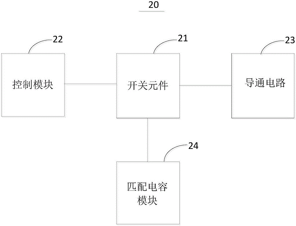
[0024] Certain terms are used throughout the description and claims to refer to particular components. Those skilled in the art should understand that hardware manufacturers may use different terms to refer to the same component. The specification and claims do not use the difference in name as a way to distinguish components, but use the difference in function of components as a criterion for distinguishing. The "comprising" mentioned in the entire specification and claims is an open term, so it should be interpreted as "including but not limited to". In addition, the term "coupled" herein includes any direct and indirect means of electrical connection. Therefore, if it is described that the first device is coupled to the second device, it means that the first device may be directly electrically connected to the second device, or indirectly electrically connected to the second device through other devices or connection means.

[0025] figure 2 is a schematic structural di...


PUM


Abstract

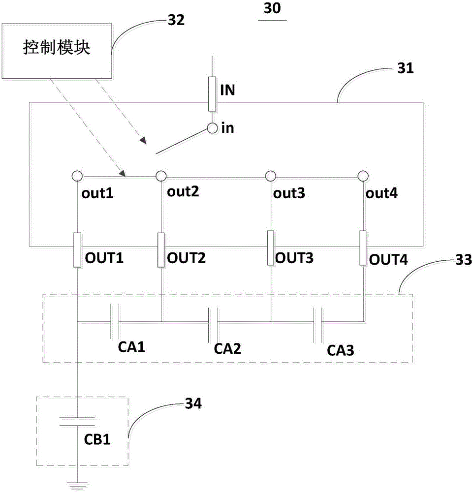
The invention discloses an antenna switch circuit and a radio frequency circuit. The antenna switch circuit comprises a switch component, a control module, a conduction circuit and a matching capacitor module, wherein the the switch component comprises an input end, multiple output ends, an input node which is arranged in the switch component and is connected with the input end, and multiple output nodes correspondingly connected with the multiple output nodes, the control module is coupled with the switch component and is used for controlling conduction of the input node and one of the multiple output nodes and conduction of the adjacent output nodes, the conduction circuit is coupled with an output end of the switch component and is used for controlling the output ends corresponding to the conducted output nodes for realizing mutual conduction in a pre-determined high frequency scope, the matching capacitor module is coupled with the output end of the switch component and comprises at least one matching capacitor, and the matching capacitor is connected with the mutually-conducted output ends or the independent output ends. The antenna switch circuit is advantaged in that power consumption is reduced, and performance of an antenna connected with the antenna switch circuit is further improved.

Description

technical field [0001] The invention relates to the field of mobile terminals, in particular to an antenna switch circuit and a radio frequency circuit. Background technique [0002] With the popularization of LTE (Long Term Evolution, Long Term Evolution) technology, mobile terminals are required to support more and more frequency bands, and the performance requirements for antennas are also getting higher and higher. Due to the wide bandwidth of LTE, in order to obtain good antenna matching, antenna switches and matching capacitors are generally added to adjust the frequency response of the antenna to obtain good antenna performance. [0003] Please also refer to figure 1 , figure 1 It is a functional block diagram of a radio frequency circuit in an existing mobile terminal. Such as figure 1 As shown, the radio frequency front end includes the main antenna ANT1, the diversity antenna ANT2, the antenna switch SP4T, multiple matching capacitors 10, the radio frequency fr...

Claims


Application Information

Patent Timeline
Patent Type & Authority Applications(China)
IPC IPC(8): H03K17/00H04B1/40
CPCH03K17/007H04B1/40
Inventor 李新倪漫利王晨
Owner SHENZHEN TINNO WIRELESS TECH
Learn More