
Terminal wire production system and production process using the equipment

A production system and terminal wire technology, applied to lines/collector parts, connected connections through deformation, electrical components, etc., can solve problems such as danger, time-consuming and labor-intensive problems, reduce defective rate, ensure system operation, The effect of reducing labor intensity

Active Publication Date: 2021-02-12
杭州三元电器有限公司
View PDF5 Cites 0 Cited by
  • Summary
  • Abstract
  • Description
  • Claims
  • Application Information

AI Technical Summary

Problems solved by technology

[0004] The above-mentioned existing technical solutions have the following defects: the above-mentioned terminal wire production process, when producing terminal wires in batches, because there must be gaps between the machines, when the staff transfers materials or semi-finished products from one machine to another, Not only time-consuming and labor-intensive, but also the possibility of danger

Method used


Image

  • Terminal wire production system and production process using the equipment
  • Terminal wire production system and production process using the equipment
  • Terminal wire production system and production process using the equipment

Examples


Embodiment 1

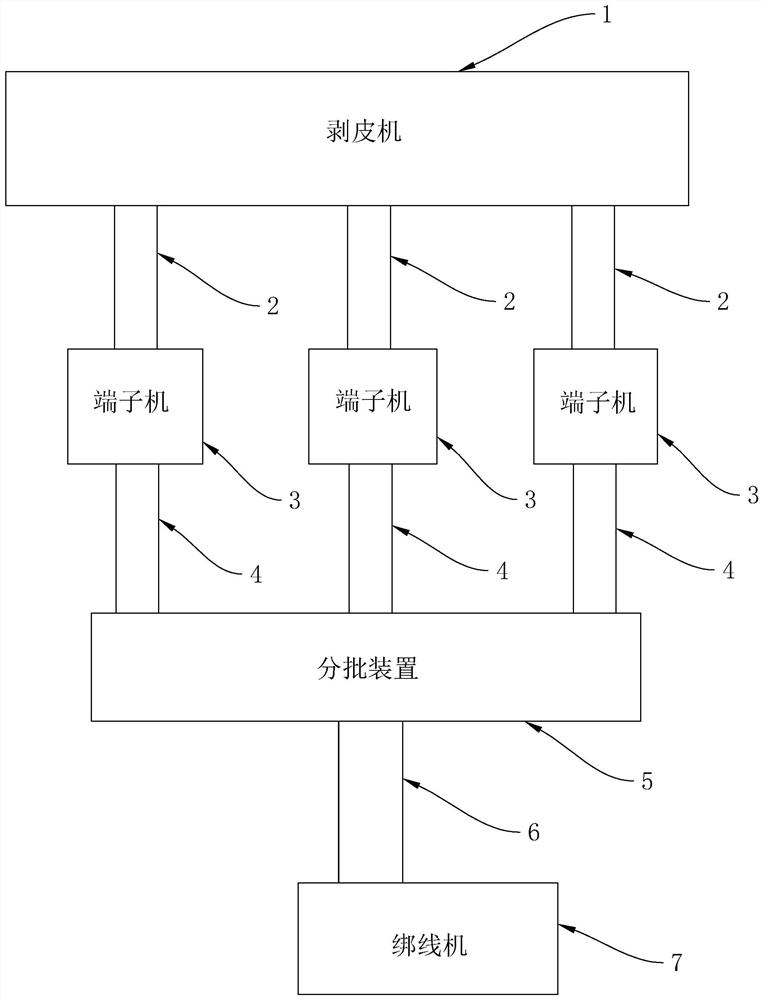
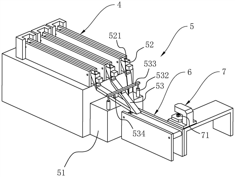
[0052]Example 1: A terminal line production system, such asfigure 1 As shown, it includes: a peeling machine 1, a plurality of terminal machines 3, and a wire binding machine 7. The peeling machine 1 is connected with a plurality of first transmission belts 2, and the other end of each first transmission belt 2 is arranged close to the corresponding terminal machine 3. Each terminal machine 3 is connected with a second transmission belt 4, and the other end of all the second transmission belts 4 is connected with a batching device 5 together. The batching device 5 is connected with a third conveyor belt 6, and the other end of the third conveyor belt 6 is arranged close to the wire binding machine 7. The worker puts the wires on the stripping machine 1 for processing. After the stripping machine 1 strips and cuts the wires, the fallen wires will be automatically transported to the terminal machine 3 by the first conveyor belt 2, and the operator of the terminal machine 3 The wires a...

Embodiment 2

[0062]Embodiment 2: A production process using a terminal line production system, the specific steps are as follows:

[0063]1. Put the long wires into the wire stripping machine, the wire stripping machine strips and cuts the long wires, and the control system 8 counts the number of stripping times of the wire stripping machine.

[0064]2. The wires processed by the wire stripping machine fall onto the first transmission belt 2 and are transported by the first transmission belt 2 to the vicinity of the terminal machine 3.

[0065]3. The wire is transferred from the first conveyor belt 2 to the terminal machine 3. The terminal machine 3 presses the hardware head to the wire end, and the control system 8 counts the number of pressing of the terminal machine 3 at the same time.

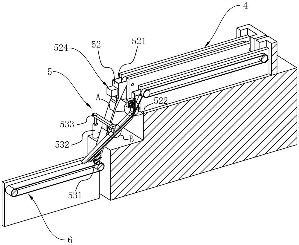
[0066]4. The terminal machine 3 drops the processed wires onto the second conveyor belt 4, and the second conveyor belt 4 transmits the wires to the lower hopper 52, and multiple wires processed by the terminal machine 3...


PUM


Abstract

The invention discloses a terminal wire production system and a production process using the equipment, belonging to the technical field of terminal wire production and processing, which includes a peeling machine, a plurality of terminal machines and a wire binding machine, the peeling machine is connected with a plurality of first transmission The other end of each first conveyor belt is set close to the corresponding terminal machine; each terminal machine is connected to a second conveyor belt, and the other ends of all second conveyor belts are connected to a batching device, and the batching device includes a frame , the frame is fixedly connected with a lower hopper, and the bottom of the lower hopper is fixedly connected with a sloping plate, and a channel is opened in the sloping plate, and the position corresponding to the bottom of the sloping plate is fixedly connected with a third conveyor belt, and the other end of the third conveyor belt is close to the binding The wire machine is set, and the slant plates are all rushed to the third conveyor belt. The stripping machine, the terminal machine and the wire binding machine are jointly connected with a control system. The invention has the effect of effectively reducing the labor intensity of the staff and improving production efficiency.

Description

Technical field[0001]The invention relates to the technical field of terminal wire production and processing, in particular to a terminal wire production system and a production process using the equipment.Background technique[0002]At present, the terminal cable, also known as Flexible Flat Cable (FFC), can choose the number and spacing of wires arbitrarily, which makes the connection more convenient, greatly reduces the volume of electronic products, reduces production costs, and improves production efficiency. It is most suitable for moving parts and motherboards. The PCB board is used as a data transmission cable between PCB boards and in miniaturized electrical equipment. When the factory produces terminal wires, it is usually necessary to strip the wires as raw materials through a stripping machine, and then pass the stripped wires through the terminal machine to perform end treatment on the wires, and then pass the treated wires through the wire binding machine. Bundle the wir...

Claims


Application Information

Patent Timeline
Patent Type & Authority Patents(China)
IPC IPC(8): H01R43/05H01R43/052H01R43/00
CPCH01R43/00H01R43/05H01R43/052
Inventor 施小英俞连娟杨飞松
Owner 杭州三元电器有限公司
Learn More