Liftable building stirring device

A mixing device and building technology, applied in the field of building mixing, can solve the problems of insufficient mixing, affecting product quality, inconvenient loading and unloading, etc., and achieve the effect of sufficient mixing, reasonable structural design, and increased quality

Inactive Publication Date: 2020-01-10
陕西锦瑞能源开发有限公司
View PDF3 Cites 0 Cited by
  • Summary
  • Abstract
  • Description
  • Claims
  • Application Information

AI Technical Summary

Problems solved by technology

[0002] Many materials need to be mixed during construction work, such as cement, lime, etc. When some materials are mixed, because the stirring device is on the mixing box, it will cause inconvenient loading and unloading, and some mixing is not sufficient, which affects the The quality of the product, in order to solve this problem, a liftable construction mixing device is needed to solve this problem

Method used


Image

  • Liftable building stirring device
  • Liftable building stirring device

Examples


Embodiment 1

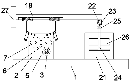
[0023] see Figure 1-2 , according to an embodiment of the present invention, a liftable building mixing device includes a workbench 1, a mixing box 21 is provided on the workbench 1, and a stirring lifting control device 20 is fixedly installed on the workbench 1. The stirring The lifting control device 20 is fixedly provided with a stirring motor 22, and the stirring motor 22 is provided with a stirring motor shaft 23, and the stirring motor shaft 23 is fixedly connected with a stirring shaft 24, and the stirring shaft 24 is provided with several groups of stirring shafts. blade 26, the stirring shaft 24 extends to the inside of the stirring box 21.

Embodiment 2

[0025] see Figure 1-2 , in a specific application, for the stirring shaft 24 and the stirring motor shaft 23, a coupling 25 is provided between the stirring shaft 24 and the stirring motor shaft 23, and the stirring shaft 24 and the stirring motor shaft 23 are fixedly connected by the coupling 25.

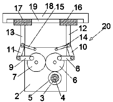
[0026] In a specific application, for the stirring and lifting control device 20 , the stirring and lifting control device 20 includes a fixed seat 2 fixedly arranged on the workbench 1 .

[0027] In a specific application, for the fixed seat 2, a positive and negative motor 3 is fixed inside the fixed seat 2, and a positive and negative motor shaft 4 is arranged on the positive and negative motor 3, and a positive and negative motor shaft 4 is fixed on the positive and negative motor shaft 4. Connected with main gear 5.

[0028] In a specific application, for the fixed seat 2, a first slave gear 6 and a second slave gear 7 are movable respectively on the fixed seat 2, and the f...


PUM


Abstract

The invention discloses a liftable building stirring device. The liftable building stirring device comprises a workbench, wherein a stirring box is arranged on the workbench, a stirring lifting control device is fixedly arranged on the workbench, a stirring motor is fixedly arranged on the stirring lifting control device, a stirring motor shaft is arranged on the stirring motor, a stirring shaft is fixedly connected to the stirring motor shaft, and a plurality of groups of stirring blades are arranged on the stirring shaft. The liftable building stirring device has the beneficial effects that,a main gear is controlled to rotate back and forth through a positive and negative motor, a first driven gear and a second driven gear are sequentially driven to rotate back and forth, so that a first supporting arm and a second supporting arm are controlled to move up and down under the auxiliary effect of a first transition arm and a second transition arm and a first limiting arm and a second limiting arm, so that a main supporting rod can move up and down to control the stirring motor and the stirring shaft to move up and down, so that the feeding and discharging of the building material during stirring are facilitated, stirring up and down during stirring is convenient, stirring is sufficient, and the stirring quality is greatly increased.

Description

technical field [0001] The invention relates to the field of building mixing, in particular to a liftable building mixing device. Background technique [0002] Many materials need to be mixed during construction work, such as cement, lime, etc. When some materials are mixed, because the stirring device is on the mixing box, it will cause inconvenient loading and unloading, and some mixing is not sufficient, which affects the The quality of the product, in order to solve this problem, therefore need a kind of liftable construction mixing device to solve this problem. Contents of the invention [0003] The object of the present invention is to provide a liftable construction mixing device to solve the problems raised in the above-mentioned background technology. [0004] Technical scheme of the present invention is realized like this: [0005] A liftable building stirring device, comprising a workbench, a stirring box is arranged on the workbench, a stirring lifting contro...

Claims


Application Information

Patent Timeline
Patent Type & Authority Applications(China)
IPC IPC(8): B28C5/16
CPCB28C5/16
Inventor 黄韬
Owner 陕西锦瑞能源开发有限公司
Why Eureka
Try Eureka