Stone dumper for pile foundation filling

A technology of riprap boats and pile foundations, which is applied in the field of machine-installed throwing and filling in bridge construction. It can solve the problems of destroying the surface layer of pile foundations and pier abutments, affecting the direction of ships, and affecting structures, and achieves the effect of improving monitoring efficiency.

Inactive Publication Date: 2020-01-10
CCCC THIRD HARBOR ENG
View PDF8 Cites 3 Cited by
  • Summary
  • Abstract
  • Description
  • Claims
  • Application Information

AI Technical Summary

Problems solved by technology

[0003] During the construction of ship machinery, the anchor position has a great influence on the protection of the pile foundation, and the anchor position affects the direction of the ship, and the wrong anchor position can easily cause the steel wire rope to scratch the pile foundation and the pier, and damage the surface of the pile foundation and the pier layer, with a significant impact on the structure

Method used


Image

  • Stone dumper for pile foundation filling
  • Stone dumper for pile foundation filling
  • Stone dumper for pile foundation filling

Examples


Embodiment 1

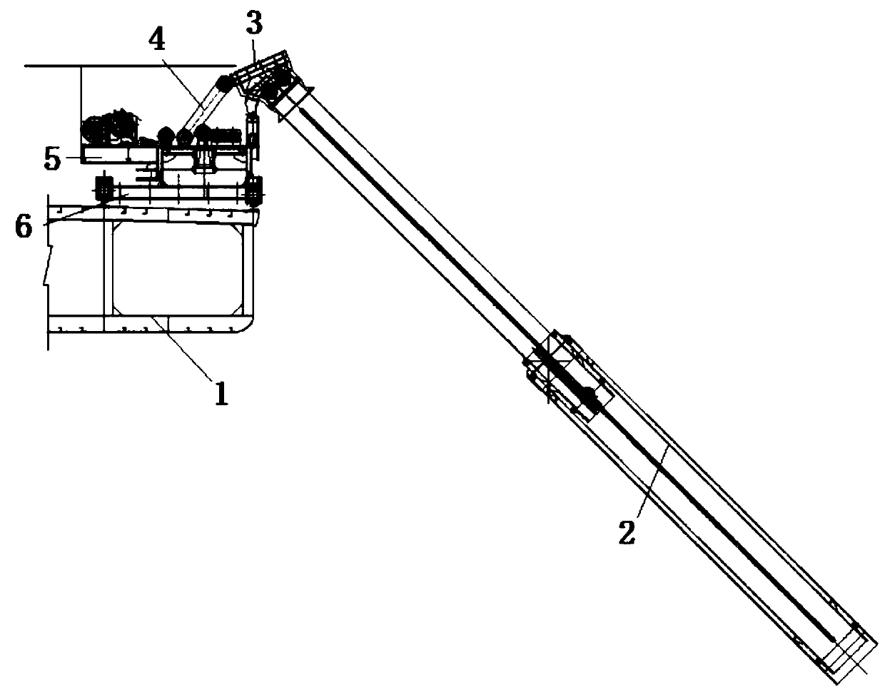
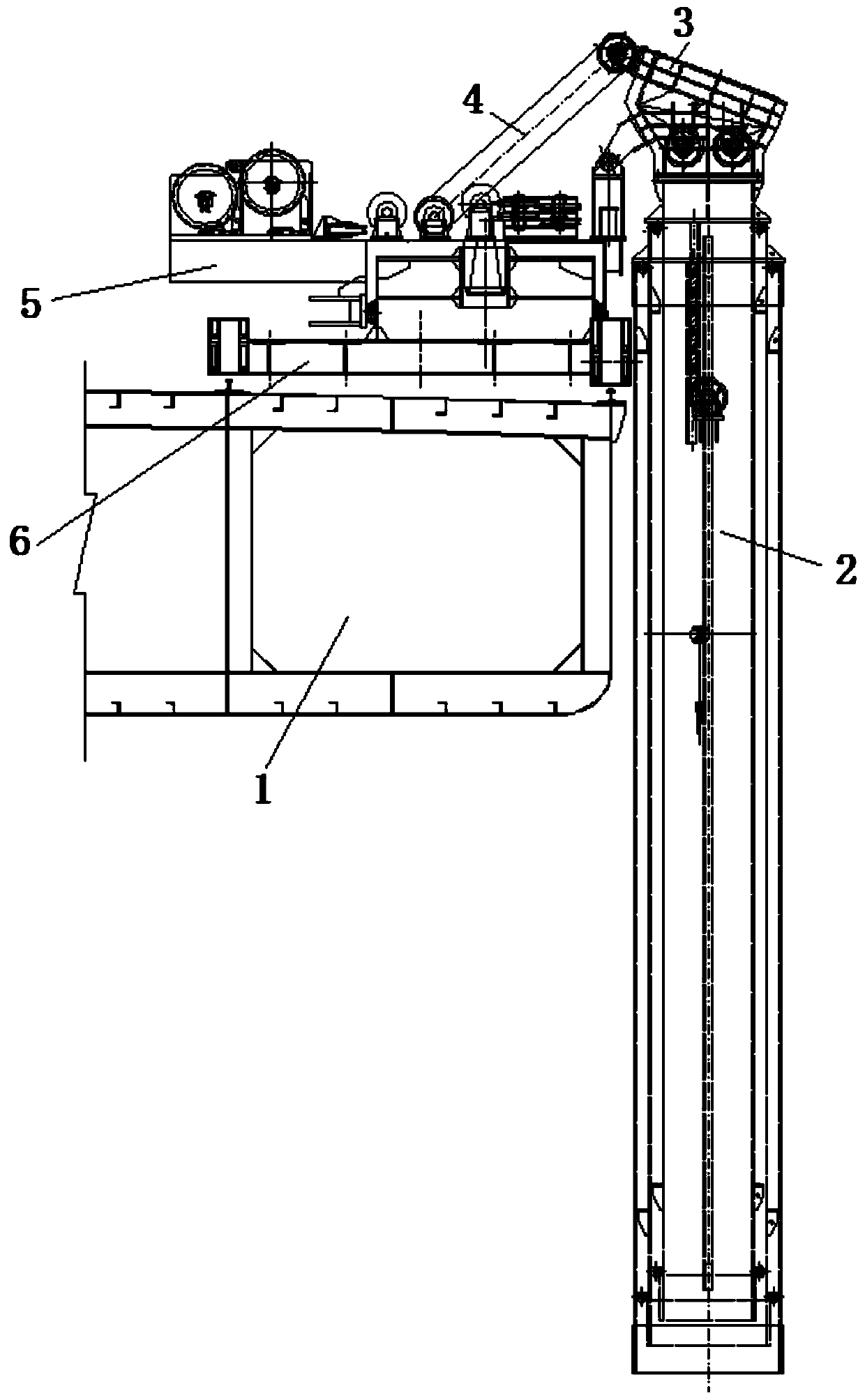
[0045] A kind of riprap boat that is used for pile foundation throwing and filling in the present embodiment, comprises hull 1, also comprises:

[0046] A chute 2, the chute 2 is arranged on the side of the hull 1, and the chute 2 is used for filling and throwing of the pile foundation;

[0047] A feed hopper 3, which is arranged on the top of the chute 2 and is used for feeding the chute 2;

[0048] Material conveying mechanism 4, the material conveying mechanism 4 is fixed on the deck of the hull 1, when filling and throwing, the material conveying mechanism 4 is used to convey the material to the chute 5, and realize the continuous feeding of the material;

[0049]The opening of the feeding hopper 3 faces upwards, the end of the material conveying mechanism 4 is arranged downward, and the feeding port 3 of the feeding hopper is arranged opposite to the end of the material conveying mechanism 4 .

[0050] In this technical solution, compared with the prior art, which uses t...

Embodiment 2

[0056] In this embodiment, the structure and adjustment of the chute are mainly introduced.

[0057] Refer to attached figure 1 As shown, it also includes a walking flat car 6 that can move along the window 1, and the walking flat car 6 is connected with the chute, and then the walking flat car 6 is controlled to realize the construction of the chute at different positions of the hull 1; a rotating platform is also provided 5. The rotating platform 5 is arranged on the upper part of the trolley 6, and the rotating platform 5 is used to realize the expansion and contraction of the chute 2, the vertical luffing and the adjustment of the left and right angles.

[0058] Compared with the prior art, by setting a turntable on the walking flat car, and then hinged the inclined chute, and by rotating the turntable and the walking flat car, throwing and filling at different positions is realized.

[0059] In this technical solution, specifically, the upper part of the chute is hinged ...

Embodiment 3

[0086] In this embodiment, the material conveying mechanism is mainly introduced.

[0087] Refer to attached Figure 5 As shown, the material conveying mechanism includes a hopper (not shown in the drawing) and a conveyor belt, and a safety distance is set between the hopper and the conveyor belt, and the safety distance is 0.6-1m.

[0088]The height of the receiving hopper is 0.7-1m. By setting the spacing, the sudden drop of bagged gravel can avoid damage to the conveyor belt. If the distance is less than 0.6m, the bagged gravel is easy to squeeze, which will lead to blockage at the receiving hopper; if the distance is greater than 1m, the gravel will fall, and it will easily damage the conveyor belt after long-term use.

[0089] The receiving hopper is made of steel, and the steel hopper is in the shape of a four-sided trumpet, with an opening on the starboard side elevation. The four corners are reinforced with channel steel, and diagonal braces are added to increase sta...


PUM


Abstract

The invention discloses a stone dumper for pile foundation filling. The stone dumper comprises a hull, a drum, a feed hopper and a material conveying mechanism, wherein the drum is arranged at the side part of the hull, and is used for pile foundation filling; the feed hopper is arranged at the upper part of the drum for feeding the drum; the material conveying mechanism is fixed on the deck of the hull, and is used for feeding the materials to the drum when filling and realizes continuous feeding of the materials; and an opening of the feed hopper faces upward, the end of the material conveying mechanism faces downward, and the feeding opening of the feed hopper and the end of the material conveying mechanism are opposite to each other. The stone dumper realizes continuous and long-distance feeding by adopting the separate material conveying mechanism to feed the drum, improves the efficiency, and expands the application range.

Description

technical field [0001] The invention belongs to the technical field of throwing and filling equipment installed in bridge construction, and in particular relates to a riprap ship used for pile foundation throwing and filling. Background technique [0002] In the construction of bridge pile foundation, according to the requirements for the safe construction of the bridge, the pier, pier foundation and pile foundation should not be damaged during construction, which is the most difficult point of pile foundation filling and throwing. The bagged gravel and dry mixture at the pile foundation must be accurately thrown and filled with a slide cylinder to prevent uneven block throwing and filling, impact on the pile foundation and scratches on the anode block of the protective layer, which will affect the service life of the pile foundation. So the chute throwing filling is the key technology of pile foundation filling and throwing. [0003] During the construction of ship machine...

Claims


Application Information

Patent Timeline
Patent Type & Authority Applications(China)
IPC IPC(8): B63B35/00B63B27/22E02D15/10
CPCB63B27/22B63B35/00E02D15/10
Inventor 毛娟龙蒋方靖杨磊吴亚飞周骏宋永华
Owner CCCC THIRD HARBOR ENG
Why Eureka
Try Eureka