Adjustable steel structure supporting member
A technology of supporting components and steel structures, which is applied to the preparation of building components on site, pillars, building structures, etc., can solve the problems of difficult adjustment of support rods, achieve the effect of improving practicability and portability, and reducing occupied space
- Summary
- Abstract
- Description
- Claims
- Application Information
AI Technical Summary
Problems solved by technology
Method used
Image

Examples
Embodiment 1
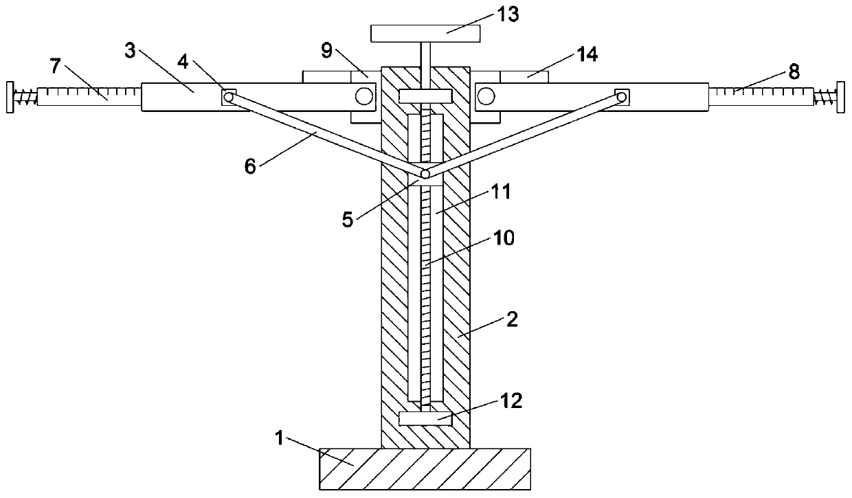
[0025] Refer to attached Figure 1-4 , this embodiment provides an adjustable steel structure support member, including a pillar 2, the pillar 2 can be fixed on the mounting seat 1 by welding or bolting, and the setting of the mounting seat 1 is convenient for installation and placement entire support structure. In addition, two sets of symmetrical first mounting blocks 9 are fixed on the pillar 2, and the support rod 3 is rotatably installed on the first mounting block 9, wherein the mounting seat 1, the pillar 2 and the support rod 3 are all steel material.
[0026] Further, an adjustment assembly for driving the support rod 3 to rotate and having a self-locking function is provided between the support rod 3 and the pillar 2; Between the rod 7 and the support rod 3 is provided a limiting assembly for restricting the sliding of the movable rod 7 , and the movable rod 7 is provided with a release assembly for releasing the restriction of the movable rod 7 by the limiting ass...
Embodiment 2
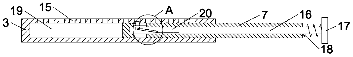
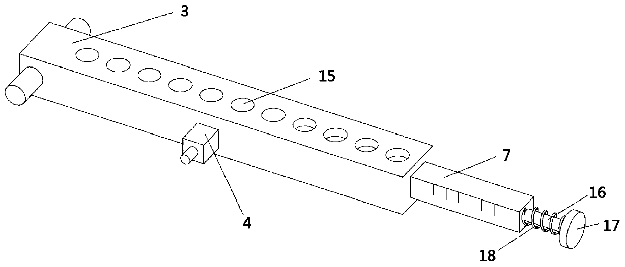
[0035] Refer to attached Figure 5 , this embodiment is improved on the basis of Embodiment 1. Specifically, the movable rod 7 is fixed with a mounting plate 29, the mounting plate 29 is fixed with a positioning rod 26, and the support rod 3 A positioning block 27 is fixed on it, and a positioning hole 28 matching the positioning rod 26 is provided on the positioning block 27 . When it is necessary to insert the movable rod 7 into the first mounting hole 19 of the support rod 3, the movable rod 7 can be positioned by inserting the positioning rod 26 into the positioning hole 28, so as to ensure that the stop rod 25 can be aligned with the support Limiting hole 15 on the rod 3.
[0036] To sum up, the steel structure support member provided by the embodiment of the present invention can be adjusted by setting an adjustment assembly with a first connecting rod 6 and a slider 5 between the pillar 2 and the rotatable support rod 3 . The sliding assembly of the screw rod 10 and t...
PUM
 Abstract
Description
Claims
Application Information