
Drilling device with guiding function

A technology of drilling device and function, applied in the field of drilling device with guiding function, can solve the problems of hole collapse, repeated measurement at stop, large drilling deviation, etc., and achieve the effect of preventing deflection

Pending Publication Date: 2020-01-10
程晨
View PDF0 Cites 0 Cited by
  • Summary
  • Abstract
  • Description
  • Claims
  • Application Information

AI Technical Summary

Problems solved by technology

There are two main types that affect the quality of drilling construction: 1. When the drilling device is drilling the building foundation, the main body of the drilling device is displaced due to vibration during the drilling process, which affects the positioning accuracy of the drilling device, resulting in The deviation of the drilling hole is relatively large; 2. Due to the uneven softness and hardness of the stratum and the oblique distribution of the soil layer during drilling, the resistance of the drill bit is uneven, which makes the drill pipe deviate and bend, so that the centerline of the drill bit and the drill pipe is different. shaft, so that the drilling is deflected, resulting in poor mud protection effect, easy diameter shrinkage, and hole collapse, so that it is difficult to lower the reinforcement cage or the forming quality is defective after lowering, which will eventually affect the quality of the pile. In order to ensure the accuracy of the drilling depth, It is necessary to stop and repeat the measurement, resulting in low efficiency of the drilling device

Method used


Image

  • Drilling device with guiding function
  • Drilling device with guiding function
  • Drilling device with guiding function

Examples


Embodiment Construction

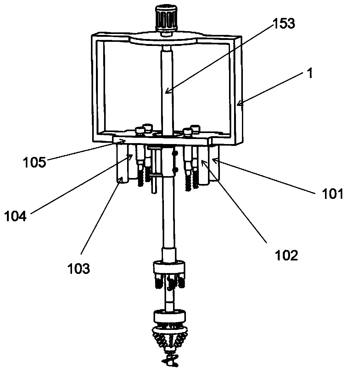
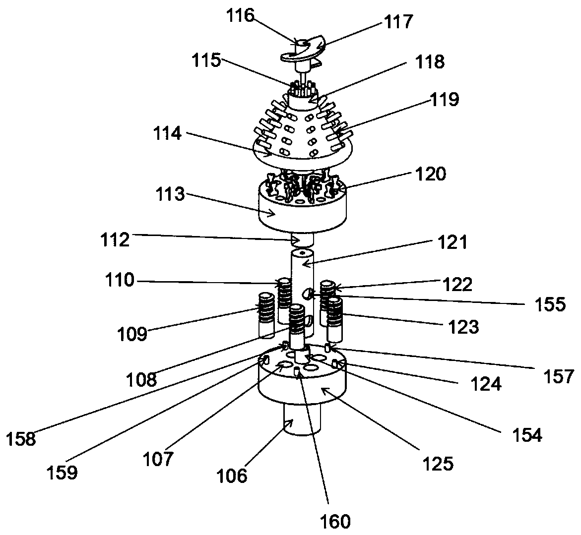
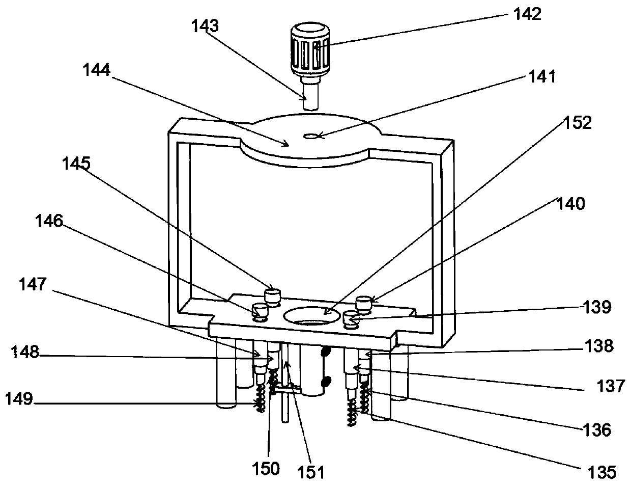
[0020] The following will clearly and completely describe the technical solutions in the embodiments of the present invention with reference to the accompanying drawings in the embodiments of the present invention. Obviously, the described embodiments are only some, not all, embodiments of the present invention. All other embodiments obtained by persons of ordinary skill in the art based on the embodiments of the present invention belong to the protection scope of the present invention.

[0021] According to an embodiment of the present invention, a drilling device with a guiding function is provided.

[0022] like Figure 1-4As shown, the drilling device with guiding function according to the embodiment of the present invention includes a support frame 1, a circular through hole 152 is arranged at the center of the bottom end of the support frame 1, and the bottom of the support frame 1 is surrounded by One electric push rod 147, two electric push rods 137, three electric pu...


PUM


Abstract

The invention discloses a drilling device with a guiding function, and relates to the technical field of building equipment. The drilling device comprises a support frame, wherein a first round through hole is formed in the center of the bottom end of the support frame, a first electric push rod, a second electric push rod, a third electric push rod and a fourth electric push rod are respectivelyarranged on the periphery of the bottom end of the support frame, the top ends of the first electric push rod, the second electric push rod, the third electric push rod and the fourth electric push rod are respectively provided with a first fixed column, a second fixed column, a third fixed column and a fourth fixed column, and the first electric push rod, the second electric push rod, the third electric push rod and the fourth electric push rod are respectively provided with a first screw rod, a second screw rod, a third screw rod and a fourth screw rod. The drilling device has the beneficialeffects that a drilling device body is prevented from being offset, the drilling positioning is more accurate, the drilling offset is prevented, the problem of deflection of the drilling hole is prevented, moreover, repeated shutdown measurement is not needed in the drilling process, and the drilling efficiency is improved.

Description

technical field [0001] The invention relates to the technical field of construction equipment, in particular to a drilling device with a guiding function. Background technique [0002] Building foundations are divided into natural foundations and artificial foundations. The foundation that can directly bear the load of the building without treatment is called the natural foundation, and conversely, the foundation that needs to be treated by the foundation treatment technology is called the artificial foundation. During the construction process of the building foundation, it is necessary to drill holes and bury piles on the foundation. The drilling machine refers to using a tool that is harder and sharper than the target object to leave a cylinder on the target object by means of rotary cutting or rotary extrusion. A general term for machines and equipment that form holes or holes. There are two main types that affect the quality of drilling construction: 1. When the drilli...

Claims


Application Information

Patent Timeline
Patent Type & Authority Applications(China)
IPC IPC(8): E21B7/04E21B15/04E21B4/04E21B10/43E21B10/44E21B10/26E21B17/10
CPCE21B4/04E21B7/04E21B10/26E21B10/43E21B10/44E21B15/006E21B15/04E21B17/1078
Inventor 程晨
Owner 程晨
Learn More