
Spherical pump with static-pressure supports
A static pressure support and spherical pump technology, applied to pumps, rotary piston type/swing piston type pump components, pump elements, etc., can solve oil film or water film damage, rotor and sliding shoe wear, increased friction, etc. problems, to achieve the effect of eliminating unbalanced force, reducing friction, and reducing power consumption
- Summary
- Abstract
- Description
- Claims
- Application Information
AI Technical Summary
Problems solved by technology
Method used
Image

Examples
Embodiment Construction
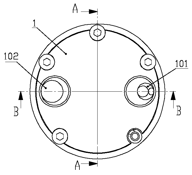
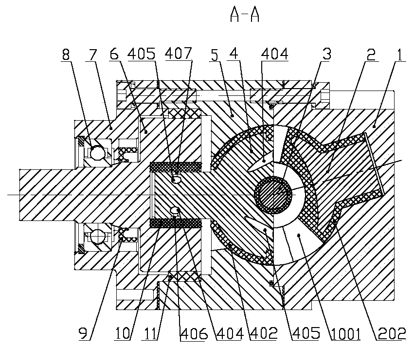
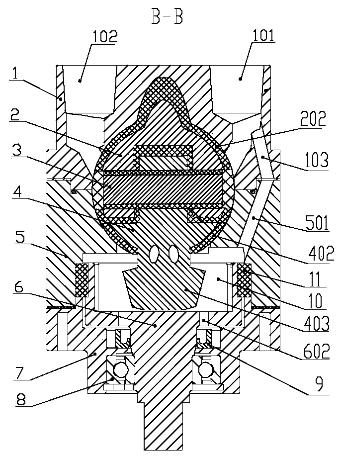
[0048] Such as Figure 1 to Figure 3 As shown, the spherical pump described in this patent includes a cylinder head 1, a piston 2, a rotating disk 4, a cylinder body 5, a main shaft 6, a main shaft support 7, etc., the cylinder body 5 and the cylinder head 1 have a hemispherical inner cavity, and the cylinder body 5 and The cylinder head 1 and the main shaft support 7 are fixedly connected by screws in turn to form a spherical pump casing with a spherical inner cavity, that is, the spherical pump stator; the piston 2, the turntable 4, and the main shaft 6 are sequentially connected to form a spherical pump rotor; The main shaft support 7 is fixedly connected to the lower end of the cylinder body 5 by screws; the piston 2 and the turntable 4 are hinged by the center pin 3, the piston shaft is inserted into the piston shaft hole 104 in the cylinder head 1, and the sliding shoe 403 at the lower end of the turntable shaft Insert it into the chute 601 on the upper end of the main s...
PUM
 Abstract
Description
Claims
Application Information