Negative compensation type large-target-surface medium-wave refrigeration infrared continuous zooming optical system

An optical system and large target surface technology, applied in optics, optical components, instruments, etc., can solve the problems of black corners, total length, and large volume of the image, and achieve the effects of reducing influence, simple compensation structure, and reducing diameter

Active Publication Date: 2020-01-10
凯迈(洛阳)测控有限公司
View PDF11 Cites 7 Cited by
  • Summary
  • Abstract
  • Description
  • Claims
  • Application Information

AI Technical Summary

Problems solved by technology

[0005] An infrared detector with a large area array scale needs to be adapted to an infrared optical system with a large target surface, otherwise black corners will appear in the image output by the system; therefore, when designing an infrared optical system, the size of the target surface must be larger than the selected infrared detector. At the same time, in order to improve the detection distance of the airborne photoelectric pod, the zoom factor of the infrared optical system also has higher requirements, so the total length and volume of the continuous infrared optical system with a large target surface will be relatively large, which is different from that of the airborne photoelectric pod. The requirements for the total length, volume, and weight of the infrared optical system with a large target surface become a contradiction; at present, there is no continuous zoom optical system in China that can adapt to a large target surface of 1280×1024 and a medium-wave cooling detector

Method used


Image

  • Negative compensation type large-target-surface medium-wave refrigeration infrared continuous zooming optical system
  • Negative compensation type large-target-surface medium-wave refrigeration infrared continuous zooming optical system
  • Negative compensation type large-target-surface medium-wave refrigeration infrared continuous zooming optical system

Examples


specific Embodiment

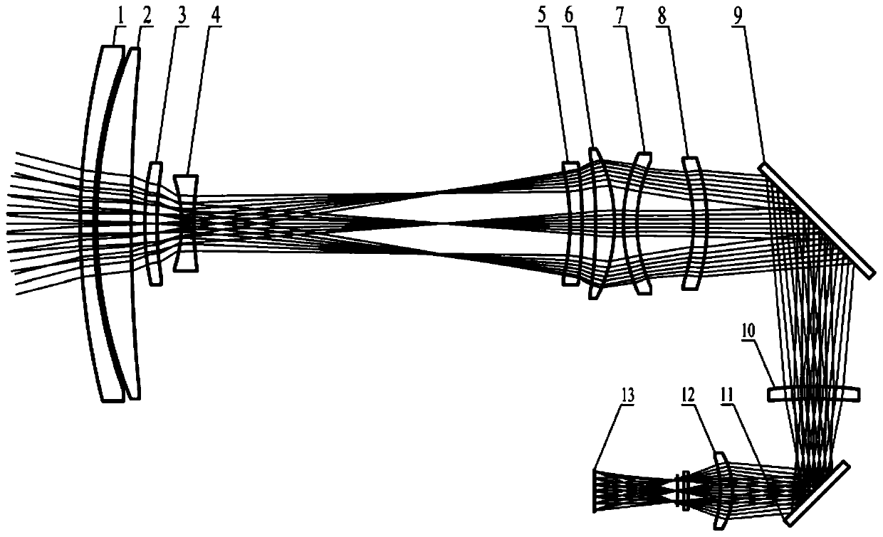
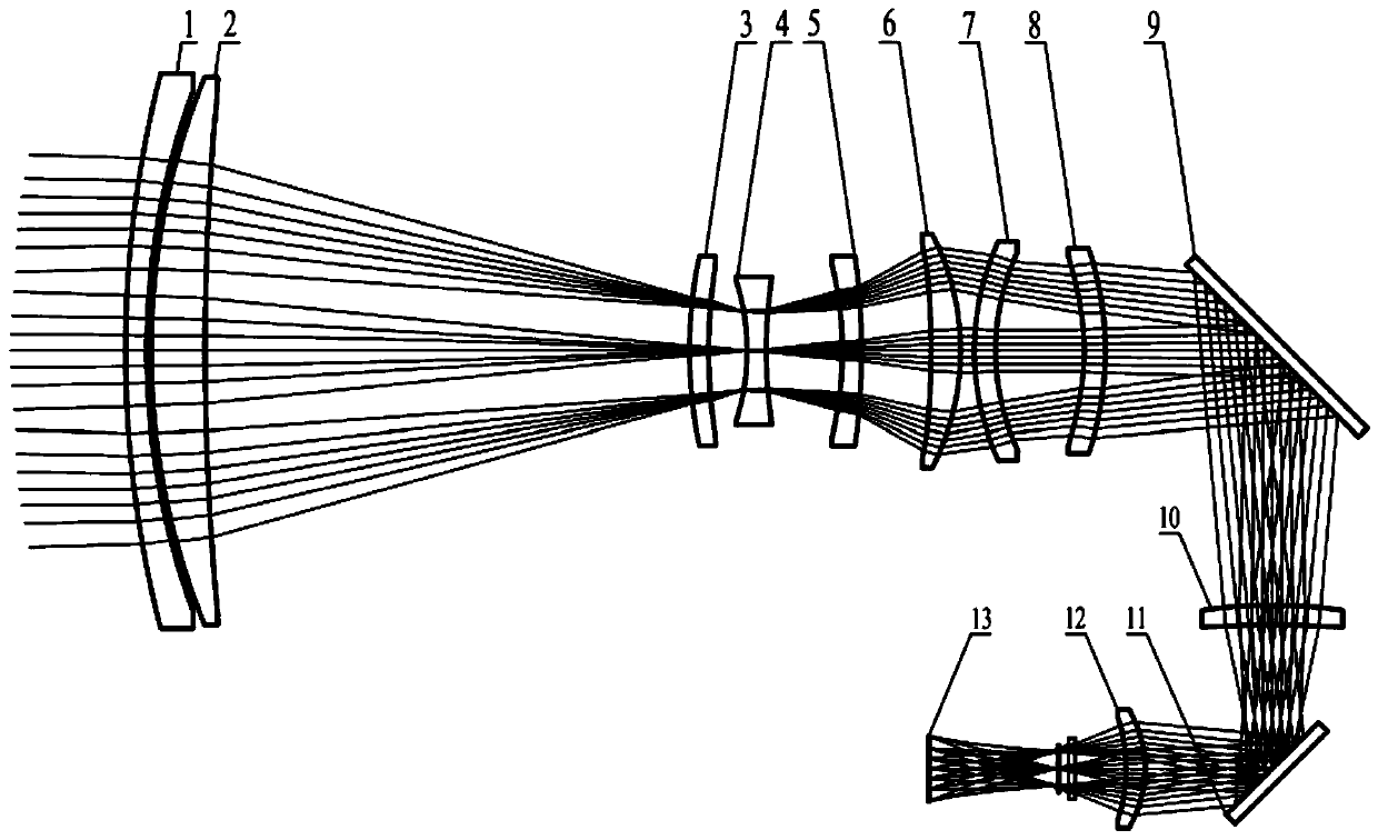
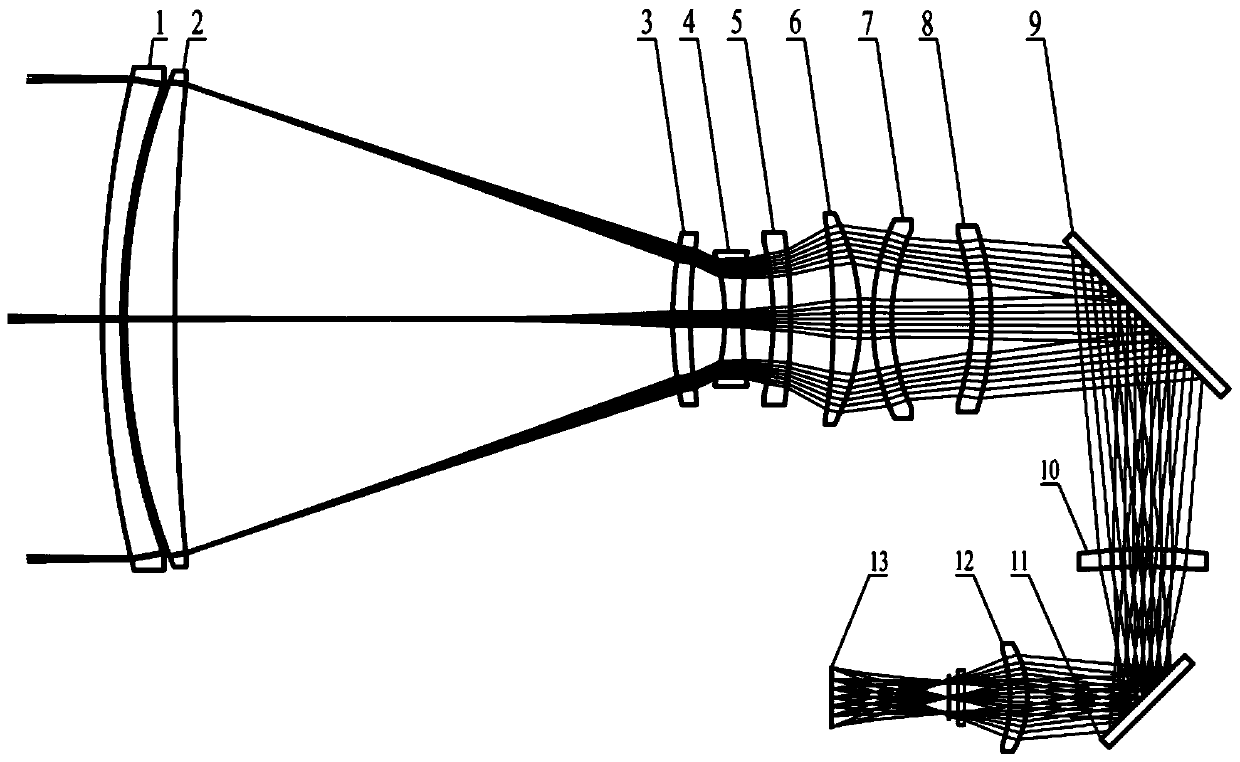
[0085] Specific technical indicators:

[0086] Waveband: 3.7μm~4.8μm; relative aperture: 1:4; focal length: 30mm~500mm; suitable for 12801024 medium-wave cooled detector with pixel size of 15μm;

[0087] Table 1: Detailed data of the embodiment of the optical system of the present invention when the focal length is 30 mm to 500 mm, including the surface shape, radius of curvature, thickness, diameter, and material of each lens. Wherein, the unit of the radius of curvature, thickness and aperture of the lens is mm;

[0088]

[0089]

[0090] Table 1

[0091] Table 2: the aspheric coefficient of the light incident side surface of the second meniscus positive lens (3) of the present invention;

[0092]

[0093]

[0094] Table 2

[0095] Table 3: the aspheric coefficient of the light incident side surface of the third meniscus positive lens (6) of the present invention;

[0096]

[0097] table 3

[0098] Table 4: According to the aspheric coefficient of the fou...


PUM


Abstract

Disclosed is a negative compensation type large-target-surface medium-wave refrigeration infrared continuous zooming optical system. The optical system adopts secondary imaging and continuous zoomingdesign, and optical and lens design to obtain a combination of only 10 lenses, has relatively high transmittance, improves system sensitivity, and effectively controls the total length of the opticalsystem; by adopting a cylindrical cam to control motion of a zoom group and a compensation group, the advantage of a simple compensation structure is achieved; a field diaphragm structure is added, sothat influence of stray light on the imaging of the system is reduced, and the signal-to-noise ratio of the system is improved; cold diaphragm is adopted, and the realization efficiency is 100%, so that the light beam energy loss is reduced, and the system sensitivity is improved; the optical axis direction of the system is changed through two plane reflecting mirrors, so that the total length ofthe optical system is shortened effectively; and the continuous zooming optical system has the advantages of high imaging quality, short optical total length, simple zoom and compensation structure,high signal-to-noise ratio and high sensitivity, and fills up the blank of a continuous zoom optical system applicable to a 1280*1024 large target surface and medium-wave refrigeration type detector in China.

Description

technical field [0001] The invention relates to the technical field of an airborne photoelectric pod infrared thermal imager, in particular to a negative-compensated large target surface mid-wave cooling infrared continuous zoom optical system. Background technique [0002] The airborne photoelectric pod system requires that the infrared thermal imager can not only realize the target search of a large field of view, but also realize the small field of view tracking and identification of long-distance targets; therefore, the optical system of the infrared thermal imager needs to be designed as a continuous zoom optical system to achieve this function; [0003] The continuous zoom infrared optical system can always keep the target image clear during the zoom process, and can realize the transformation of any field of view within the zoom range, ensuring that when it is applied to the airborne photoelectric pod, the system will not lose the tracking target during the continuous...

Claims


Application Information

Patent Timeline
Patent Type & Authority Applications(China)
IPC IPC(8): G02B15/177G02B27/00
CPCG02B15/177G02B27/0012
Inventor 吴海清曾宪宇李同海刘士华赵新亮崔莉田海霞
Owner 凯迈(洛阳)测控有限公司
Why Eureka
Try Eureka