
An illumination device for an optical system of a reader apparatus

A lighting device and optical system technology, applied in the field of marking devices, safety tracking and traceability systems, to achieve maximum optical efficiency and reduce specular reflection

Active Publication Date: 2020-01-10
SICPA HLDG SA
View PDF14 Cites 0 Cited by
  • Summary
  • Abstract
  • Description
  • Claims
  • Application Information

AI Technical Summary

Problems solved by technology

This illumination device (without requiring an excitation filter) solves the above-mentioned problem of strong specular reflection from surfaces that can saturate the photosensor and prevent reading or reading of codes printed with absorbing inks. Prevents reading of luminescent codes

Method used


Image

  • An illumination device for an optical system of a reader apparatus
  • An illumination device for an optical system of a reader apparatus
  • An illumination device for an optical system of a reader apparatus

Examples


Embodiment Construction

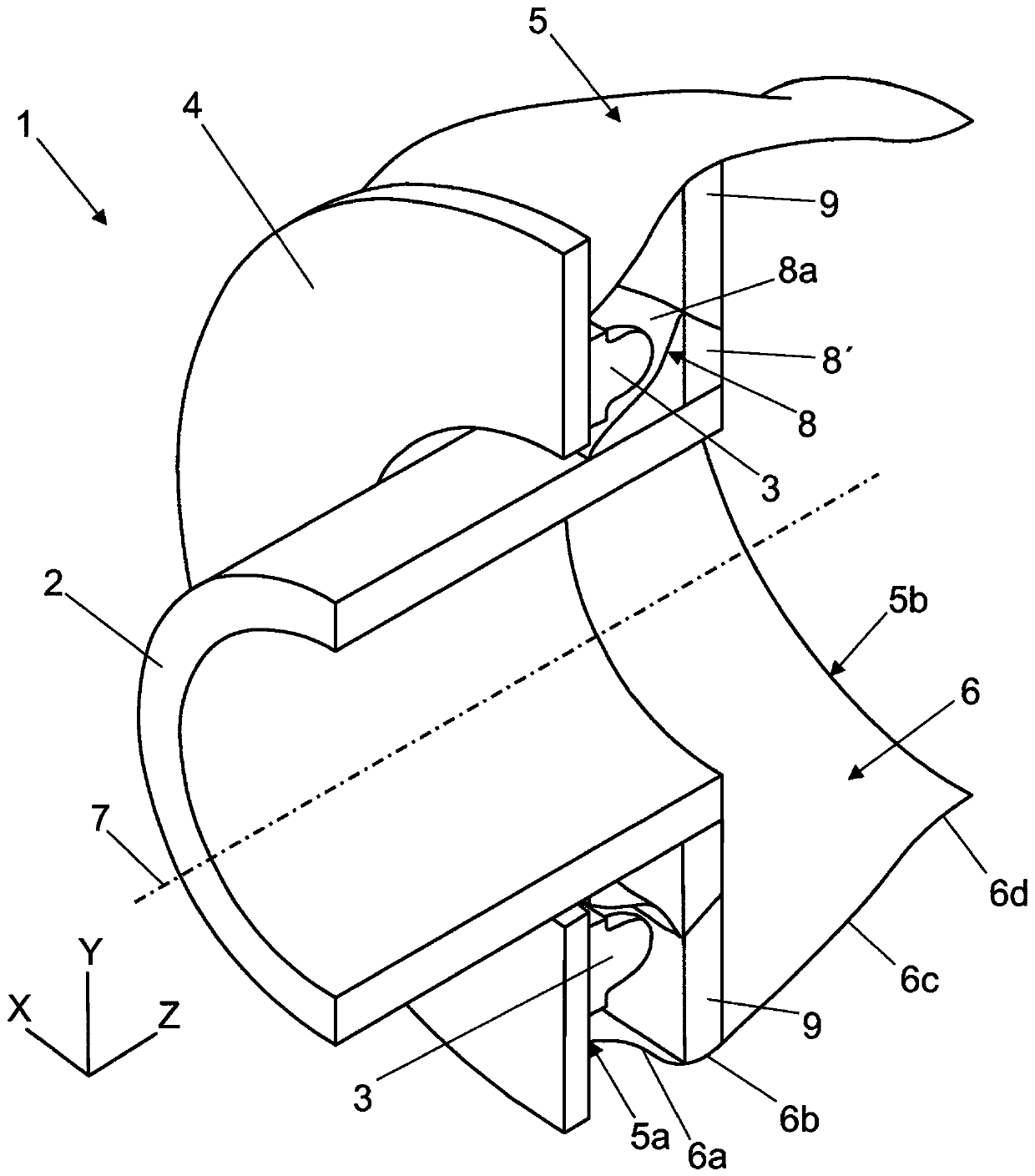
[0047] The invention relates to an illumination arrangement for an optical system of a reader device. figure 1 The main components of the lighting device 1 according to a longitudinal section along the central axis 7 are shown in perspective. The lighting device enables reading and / or detection of luminescent markings or symbols printed on the item by the optical system of the reader device. The axis Z represents the longitudinal dimension, the axis Y represents the vertical direction, and the axis X represents the depth of the lighting device 1 .

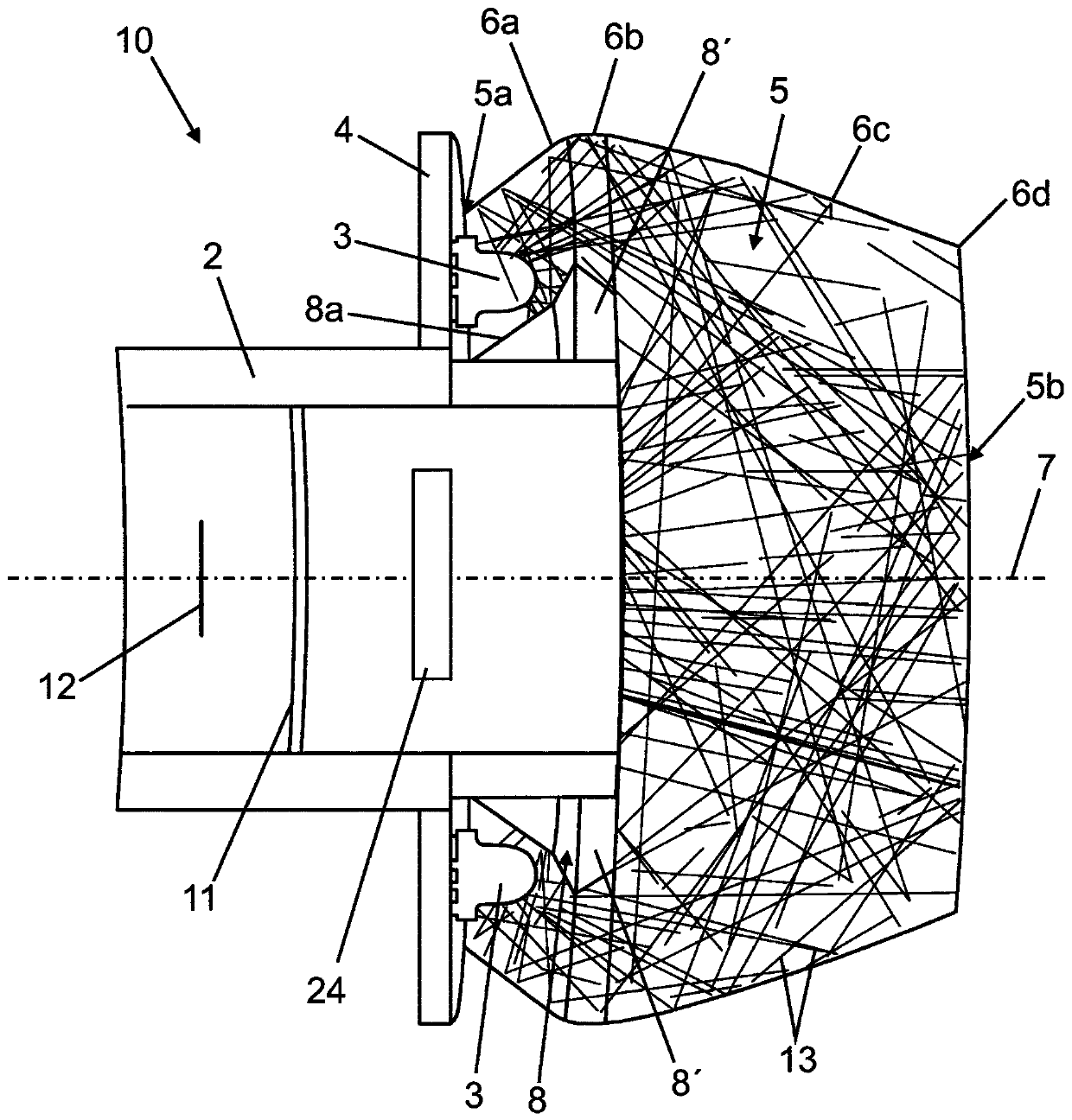
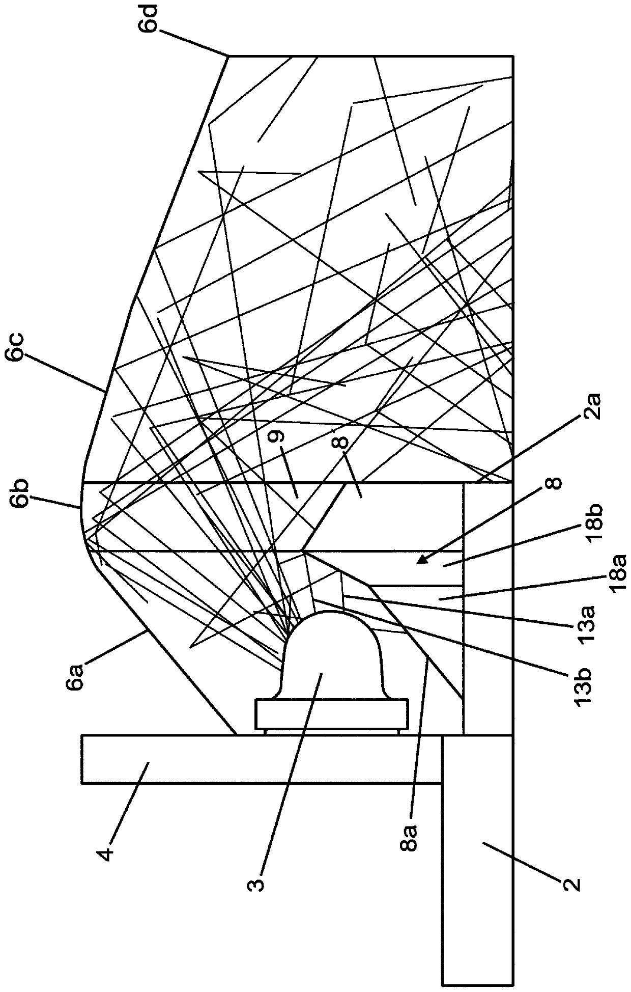
[0048] Such as figure 1 As shown, the illumination device includes an annular hollow body 2 configured to receive a light field acquisition device (optical capture component), a light source 3 configured around the outer portion of the annular hollow body 2 for exciting a marker, and guiding the light from the light source 3 To the external light reflector 5 of the region at the distal end 5 b of the external light reflector 5 . ...


PUM


Abstract

An illumination device for an optical system of a reader apparatus, comprising a light source (3) disposed concentrically around an annular hollow body (2), an external light reflector (5) for redirecting light to illuminate a zone at its distal end (5b), and a reflector element (8) with a mirror finish outer surface (8a). The internal wall (6) of the external light reflector (5) is made of reflective material, having a first portion (6a) with increasing cross sections from a proximal end (5a) to a first region (6b) with maximum cross section, and a second portion (6c) with decreasing cross sections from the first region (6b) to a second region (6d) with minimum cross section. The reflector element (8) is arranged in front of the light source (3) to redirect light towards the first portion(6a) of the external light reflector (5). The illumination device (1) achieves, in a reduced space, high optical efficiency and uniform illumination on the mark to read, avoiding specular reflection.

Description

technical field [0001] The present invention is included in the field of security tracking and traceability systems, and more particularly in the field of devices for reading and / or authenticating markings printed on objects, such as luminescent markings printed with luminescent ink, etc., Wherein the mark can be a pattern, a logo, a 1D or 2D barcode, or any other symbol or identification code. In particular, the present invention relates to optics and lighting used by indicia readers to illuminate and capture indicia. The reader may be eg a handheld device, an optical scanner or any reading device installed on the production / distribution line. Background technique [0002] Handheld readers are often used to scan items or markings on the surface of an object. The marking may be implemented as a linear barcode, matrix barcode or any other pattern comprising identification data corresponding to the item. Markings on the surface of an item are often invisible or nearly invis...

Claims


Application Information

Patent Timeline
IPC IPC(8): G06K7/10
CPCG06K7/10722G06K7/10742
Inventor F·霍特P·森佩雷T·迪诺伊伍N·杜卡
Owner SICPA HLDG SA
Learn More