Automatic injector

A technology of automatic injectors and components, applied in the field of medical devices, can solve the problems of low reliability, difficult assembly, high product cost, etc., and achieve the effects of avoiding repeated use, reducing parts and components, and simple structure

Pending Publication Date: 2020-01-14
SUZHOU JIASHU MEDICAL TECH CO LTD
View PDF3 Cites 2 Cited by
  • Summary
  • Abstract
  • Description
  • Claims
  • Application Information

AI Technical Summary

Problems solved by technology

[0002] Existing disposable auto-injectors are very complicated in design principles, resulting in a large number of parts

Method used


Image

  • Automatic injector
  • Automatic injector
  • Automatic injector

Examples


Embodiment 1

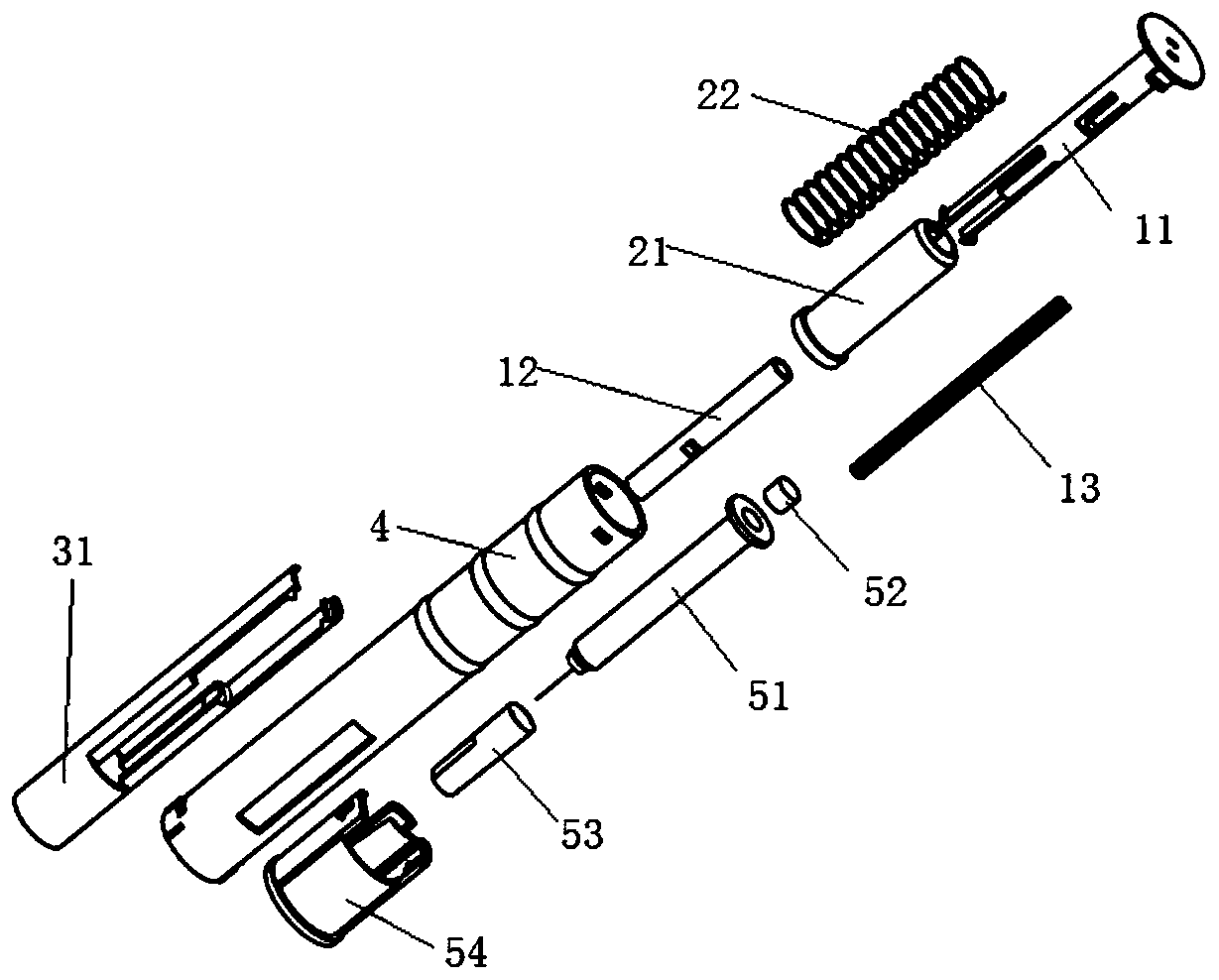
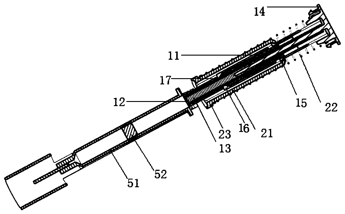
[0049] Such as Figure 1-6 As shown, an automatic injector includes a main shaft 11, a main spring sleeve 12, a main spring 13, an activation sliding sleeve 21, an auxiliary spring 22, a syringe sliding sleeve 31, a housing 4 and a prefilled syringe 51;

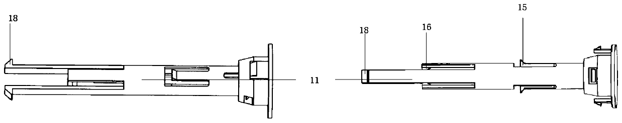
[0050] The shaft body of the main shaft 11 is hollow, one end of which is closed and has a first flange 14, and several elastic first bumps are arranged on the shaft body 11 according to the distance from the first flange 14 from near to far. 15 and the second protrusion 16, the first protrusion 15 protrudes toward the outer surface of the shaft, and has an axial guide slope toward the first flange 14, and the second protrusion 16 protrudes toward the inner surface of the shaft The protrusion has an axial guide slope towards the first flange 14;

[0051] In the assembled state, the main spring sleeve 12 is located in the shaft body of the main shaft 11, one end of which is closed and the other end is open, the closed end can...

Embodiment 2

[0058] Such as image 3 As shown, in this embodiment, the shaft body wall where the first and second protrusions 15, 16 are located is hollowed out to form a strip with elasticity, and the first and second protrusions 15, 16 are located on the strip, When the elastic strips of the first and second projections 15, 16 were in a straight line, the strip width of the second projection 16 was greater than the width of the groove 24 in the starting sliding sleeve 21, so that the second projection The strip of the block 16 will not be entirely located in the space of the groove 24 , so as to ensure that the inner wall of the starting sliding sleeve 21 can press the second protrusion 16 tightly.

Embodiment 3

[0060] In this embodiment, the closed end of the main spring sleeve 12 is perforated, which is conducive to the timely discharge of the air between the main spring sleeve 12 and the piston of the prefilled syringe 51. After the injection is started, the main spring sleeve 12 and the piston 52 quickly Access without barriers.


PUM


Abstract

The invention provides an automatic injector. The automatic injector is characterized by comprising a propelling assembly, a starting assembly, a trigger assembly and a casing, wherein the propellingassembly is located in the starting assembly and comprises a propelling component and a limiting component, the propelling component is limited by the limiting component through clamping, and the starting assembly ensures brake of the propelling assembly before injection by the limited form of the propelling assembly; the trigger assembly accommodates a pre-filling needle barrel and pushes the starting assembly to separate from a brake position after injection begins; and the casing coats the whole injector.

Description

technical field [0001] The invention relates to the field of medical devices, in particular to a disposable automatic injection device. Background technique [0002] Existing disposable auto-injectors are very complex in design principles, resulting in a large number of parts, generally more than 15, so the reliability is not high, the assembly is difficult, and the final product cost is too high. [0003] CN110237366A discloses a medical injection device, which includes an outer cylinder and a pen cap. One end of the outer cylinder is provided with a detachable drug storehouse, and a replaceable standard cartridge medicine bottle is arranged in the drug storehouse. The inside of the outer cylinder is close to one end of the drug storehouse. A fixed sleeve is provided, and the inner axial movement of the fixed sleeve is provided with a push rod seat. The inside of the push rod seat is provided with a transmission ring that can be engaged with the end of the transmission rod....

Claims


Application Information

Patent Timeline
IPC IPC(8): A61M5/20A61M5/31A61M5/50A61M5/46
CPCA61M5/2033A61M5/31A61M5/46A61M5/50A61M2005/2006A61M2005/2026
Inventor 熊长艳陈红丹
Owner SUZHOU JIASHU MEDICAL TECH CO LTD
Why Eureka
Try Eureka