Multi-layer forged and pressed stirring head for friction stir welding
A friction stir welding and stirring head technology, which is used in welding equipment, non-electric welding equipment, metal processing equipment, etc., can solve the problems of uneven depth direction of weld structure and increased flash, and achieve uniform depth direction and reduce forging. The effect of pressure, up and down flow is sufficient
- Summary
- Abstract
- Description
- Claims
- Application Information
AI Technical Summary
Problems solved by technology
Method used
Image

Examples
Embodiment Construction
[0023] The present invention will be further described in detail below in conjunction with the accompanying drawings and specific embodiments.
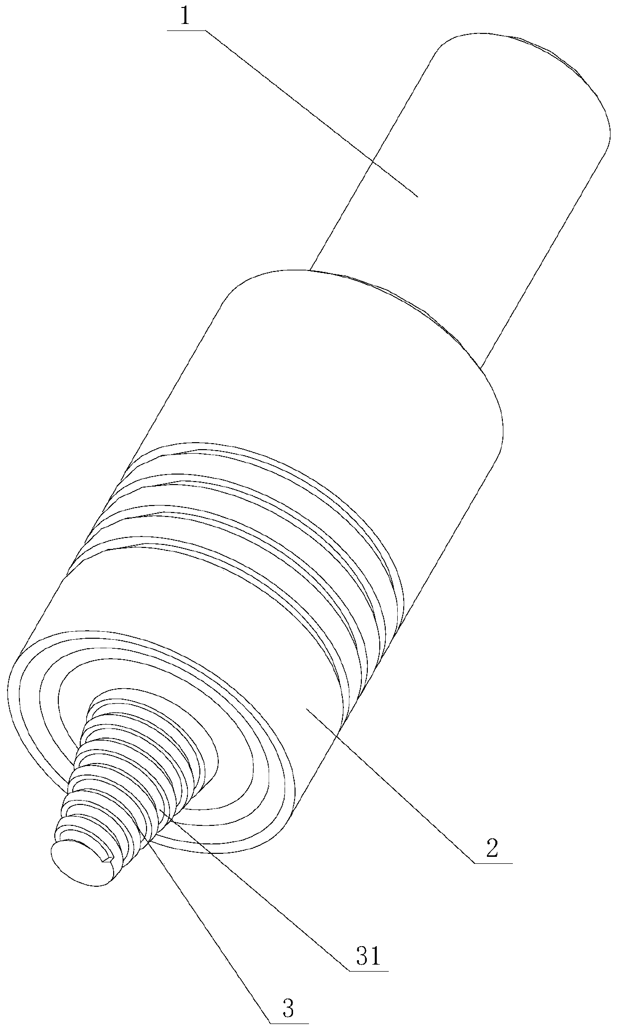
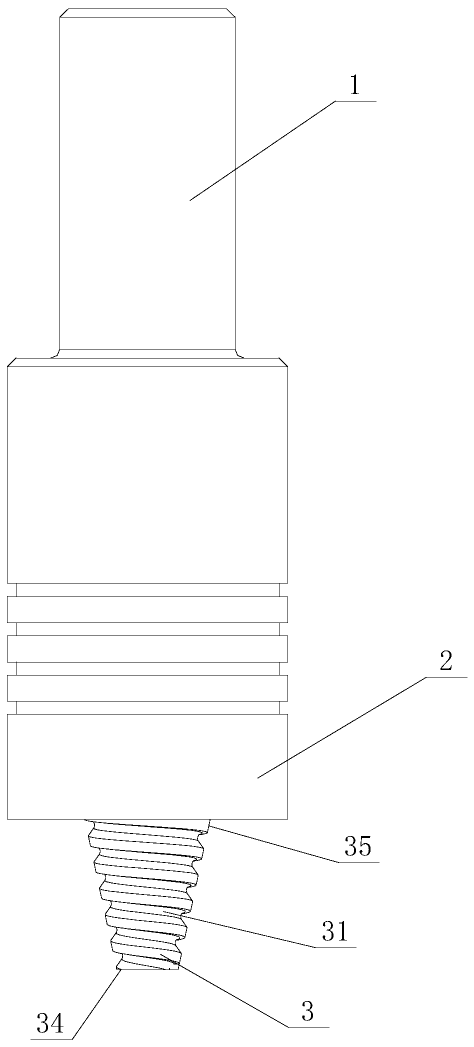
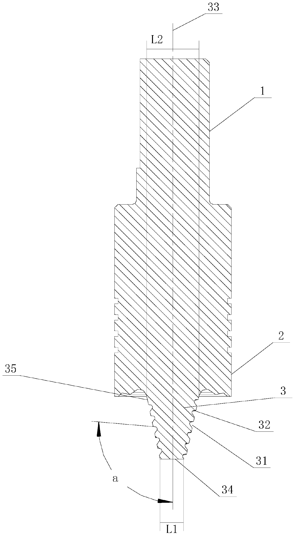
[0024] Figure 1 to Figure 4 It shows an embodiment of the multi-layer forging type stirring head used for friction stir welding of the present invention, including the clamping part 1, the shaft shoulder part 2 and the stirring pin 3 connected in sequence, and the peripheral side of the stirring pin 3 is provided with a spiral The top surface of the groove 31 and the spiral groove 31 forms a forging surface 32 . During welding, the clamping part 1 is used for clamping, the stirring pin 3 generates heat energy through rotational friction, and the shoulder part 2 is used to form forging. Compared with the traditional structure, the stirring head forms a multi-layer spiral groove 31 on the peripheral side of the stirring needle 3, and the top surface of the spiral groove 31 forms a forging surface 32, which is brought by the multi-laye...
PUM
 Abstract
Description
Claims
Application Information
 - Generate Ideas
- Intellectual Property
- Life Sciences
- Materials
- Tech Scout
- Unparalleled Data Quality
- Higher Quality Content
- 60% Fewer Hallucinations
Browse by: Latest US Patents, China's latest patents, Technical Efficacy Thesaurus, Application Domain, Technology Topic, Popular Technical Reports.
© 2025 PatSnap. All rights reserved.Legal|Privacy policy|Modern Slavery Act Transparency Statement|Sitemap|About US| Contact US: help@patsnap.com