Cloth winding device for garment making

A winding device and fabric technology, which is applied in the direction of winding strips, thin material processing, transportation and packaging, can solve the problems of difficulty in ensuring the flatness of the fabric, wrinkling of the fabric, and creases in the fabric, so as to improve the winding speed. quality, improve fabric quality, and ensure the effect of tension

Inactive Publication Date: 2020-01-14
天门市丰煜服饰有限公司
View PDF1 Cites 5 Cited by
  • Summary
  • Abstract
  • Description
  • Claims
  • Application Information

AI Technical Summary

Problems solved by technology

[0002] After the fabric processing is completed, the fabric needs to be rolled up, that is, the processed fabric is taken up on the fabric take-up roller, so as to facilitate the transportation between each process and the final storage. The traditional take-up device consists of a simple take-up stand and a take-up Composed of rolling rollers, the existing winding device is not very convenient to use, and it is easy to cause the fabric to wrinkle when winding
[0003] In the Chinese Patent Publication No. CN209143288U, a cloth rolling de

Method used


Image

  • Cloth winding device for garment making
  • Cloth winding device for garment making
  • Cloth winding device for garment making

Examples


Embodiment 1

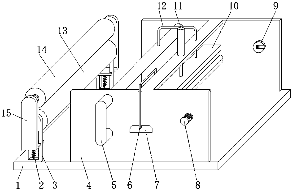
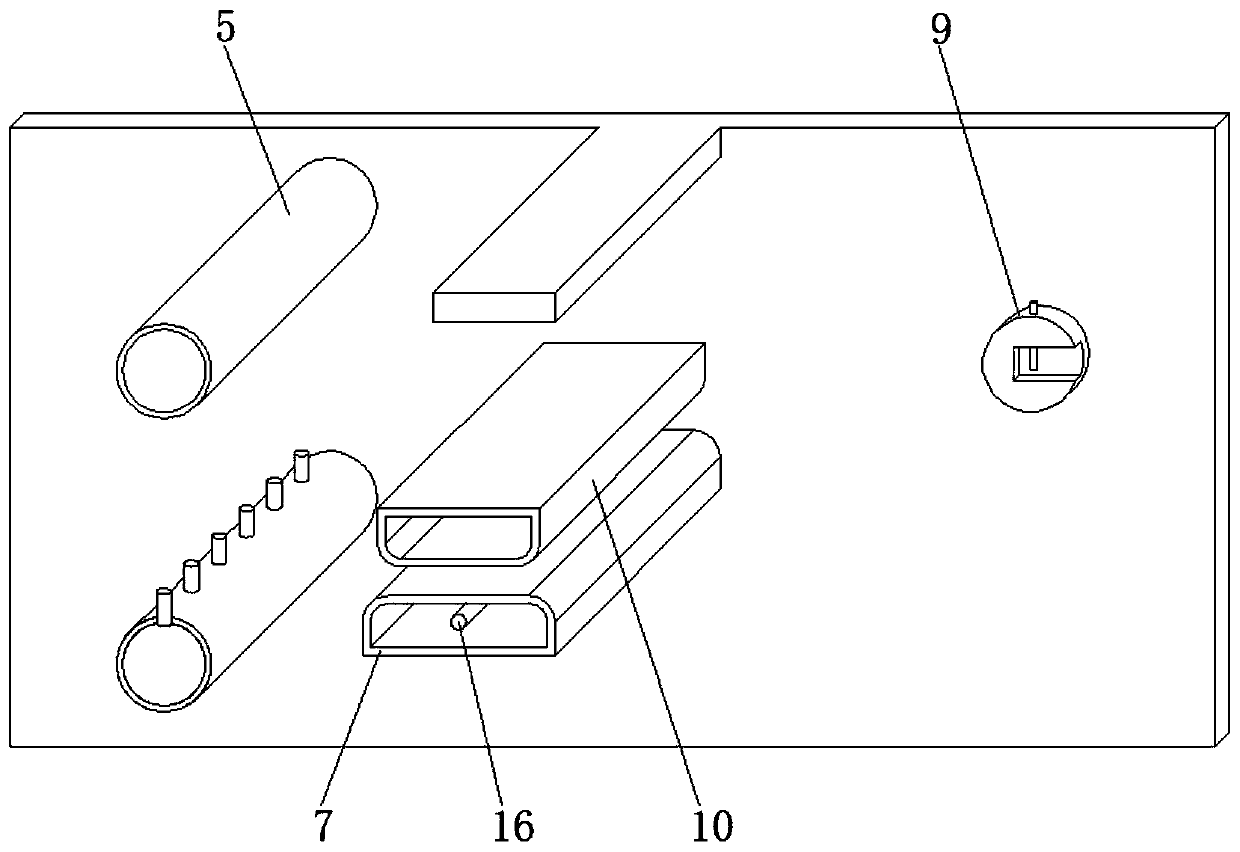
[0026] Reference Figure 1-2 , A cloth winding device for clothing processing, comprising a base 1, a fixing frame 3 and a mounting frame 4 are welded on both sides of the top outer wall of the base 1, and the fixing frame 3 is provided with a pressing mechanism, one of the fixing frame 3 A U-shaped tube installation hole is opened on the side outer wall, and the inner wall of the U-shaped tube installation hole is inserted with a U-shaped tube 5. For the air nozzle, the middle of the inner wall of the mounting frame 4 is fixed with the ironing box 7 by screws, and the top outer wall of the mounting frame 4 is fixed with a hydraulic cylinder 11 by screws. The bottom end of the piston rod of the hydraulic cylinder 11 is fixed with a pressure plate 10 by screws, and the pressure plate 10 is located directly above the ironing box 7.

[0027] In the present invention, both the outer wall of one side of the ironing box 7 and the top outer wall of the pressure plate 10 are provided wi...

Embodiment 2

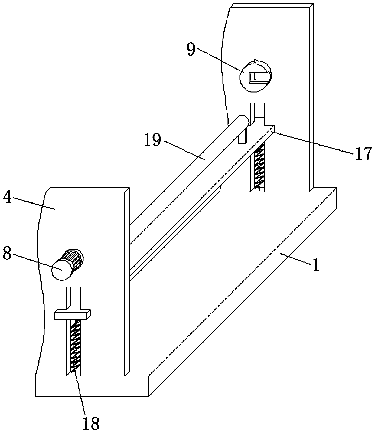
[0035] Reference image 3 , A cloth winding device for clothing processing. The inner walls of the mounting frame 4 are provided with sliding frame slide grooves, and the inner wall of the sliding frame slide groove is slidably connected with a sliding frame 17, the bottom outer wall of the sliding frame 17 and the top of the base 1 A support spring 18 is welded between the two sides. The inner wall of the sliding frame 17 is provided with squeeze roller mounting holes. The inner wall of the squeeze roller mounting hole is connected with a squeeze roller 19 through a bearing. The squeeze roller 19 is located on the connecting roller 9. Directly below.

[0036] Working principle: The support spring 18 exerts an upward pushing force on the sliding frame 17, which drives the squeeze roller 19 to attach to the wound fabric to ensure the flatness of the wound fabric.


PUM


Abstract

The invention discloses a cloth winding device for garment making. The cloth winding device comprises a base. A fixed rack and a mounting rack are welded to the two sides of the outer wall of the topof the base correspondingly, and a pressing mechanism is arranged in the fixed rack. A U-shaped pipe mounting hole is formed in the outer wall of one side of the fixed rack, and a U-shaped pipe is connected to the inner wall of the U-shaped pipe mounting hole in an inserted manner. Air spray holes are formed in the top inner wall and the bottom inner wall of the U-shaped pipe. Air spray nozzles are connected to the inner walls of the air spray holes in an inserted manner. An ironing box is fixed to the middle of the inner wall of the mounting rack through screws, a hydraulic cylinder is fixedto the outer wall of the top of the mounting rack through screws, and a press plate is fixed to the bottom end of a piston rod of the hydraulic cylinder through screws. According to the cloth windingdevice, humidity of cloth can be increased, the cloth is ironed through the ironing box and the press plate, water in the cloth is removed through drying, folds of the cloth can be eliminated, the cloth quality can be improved easily, the tension degree of the cloth between a pressing roller and a connecting roller can be guaranteed, and the winding quality can be improved easily.

Description

Technical field [0001] The invention relates to the technical field of clothing processing devices, in particular to a cloth winding device for clothing processing. Background technique [0002] After the fabric is processed, the fabric needs to be wound, that is, the processed fabric is wound on the fabric winding roller for transportation and final storage between processes. The traditional winding device consists of a simple winding rack and a winding roller. It is composed of reeling rollers, and the current reeling device is not convenient to use, and it is easy to cause the phenomenon of fabric wrinkling during rewinding. [0003] In the Chinese Patent Publication No. CN209143288U, a fabric winding device for clothing production and processing is disclosed, including a winding frame. The inside of the winding frame is fixedly connected with a flattening frame, which passes through the pressing plate and rolling while winding. The rod flattens the fabric to prevent the fabric...

Claims


Application Information

Patent Timeline
IPC IPC(8): B65H23/26B65H18/26
CPCB65H18/26B65H23/26
Inventor 林顺英
Owner 天门市丰煜服饰有限公司
Why Eureka
Try Eureka