
Construction method of a corrugated steel culvert

A construction method and technology of corrugated steel pipes, which are applied in the construction field of corrugated steel pipe culverts, can solve problems such as poor mechanical performance, poor durability of corrugated steel structures, and poor mechanical performance

Active Publication Date: 2021-09-10
ZHENGPING ROAD & BRIDGE CONSTR CO LTD +4
View PDF8 Cites 0 Cited by
  • Summary
  • Abstract
  • Description
  • Claims
  • Application Information

AI Technical Summary

Problems solved by technology

[0004] However, in the actual use process, the corrugated steel structure pipe culvert has the following defects: First, the pipe diameter is too small: the pipe diameter is usually not greater than 3m, and the space provided is limited, which cannot meet the requirements of the main line pipe gallery and the larger branch line pipe gallery Second, there is a lack of simple and effective splicing methods. At present, there are two main longitudinal splicing methods for corrugated steel pipe structures. The first is welding, and the second is flange and bolt connection, but the first method The construction speed is slow and the labor cost is high. Although the second method is faster in construction, it does not give full play to the structural characteristics and advantages of corrugated steel, and damage and leakage are prone to occur in the longitudinal connection parts; third, corrugated steel Poor structural durability and poor mechanical performance, especially for long-distance large-diameter spliced ​​pipe culverts, which have poor integrity and poor mechanical performance. Many damaged parts will inevitably appear, and the later maintenance workload will be large

Method used


Image

  • Construction method of a corrugated steel culvert
  • Construction method of a corrugated steel culvert
  • Construction method of a corrugated steel culvert

Examples


Embodiment Construction

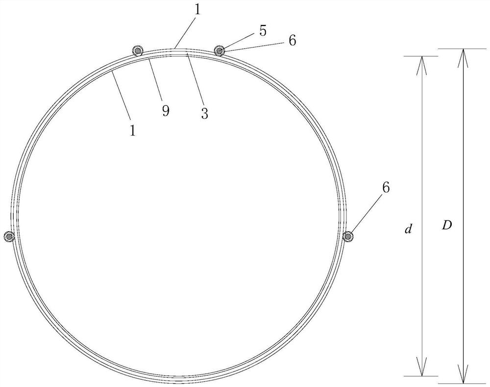
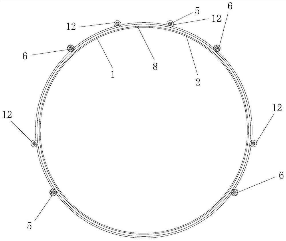
[0103] Such as Figure 12 A construction method of a corrugated steel culvert shown, the constructed pipe culvert includes a base 16 and a corrugated steel culvert supported on the base 16, the base 16 is a cast-in-place reinforced concrete base; the base 16 and the corrugated steel pipe culverts are arranged along the longitudinal extension direction of the constructed pipe culverts; a filling layer 15 is arranged outside the constructed pipe culverts, and the base 16 and the corrugated steel pipe culverts are all located in the filling soil layer 15. See Figure 10 ; The bottom of the base 16 and the bottom of the filling layer 15 are arranged on the same horizontal plane;

[0104] combine figure 1 , figure 2 , image 3 , Figure 4 , Figure 5 , Figure 7 , Figure 8 and Figure 9 , the corrugated steel culvert includes a pipe culvert body spliced ​​by a plurality of pipe culvert splicing sections 1 and a prestressed reinforcement structure arranged outside the pip...


PUM


Abstract

The invention discloses a construction method of a corrugated steel pipe culvert, in which a plurality of said pipe culvert splicing sections are respectively spliced ​​and constructed from back to front, comprising the steps of: A1, splicing construction of the rear end splicing section; A2, splicing of the next splicing section Construction; A3. Repeat step A2 several times until the splicing construction process of all pipe and culvert splicing sections on the rear side of the front-end connection section is completed; A4. Splicing construction of the front-end connection section. The present invention is reasonable in design, simple in construction, and good in use effect. The spliced ​​corrugated steel culvert is reinforced segmentally by using a prestressed reinforcement structure, and the structure and arrangement position of each prestressed tendon group in the prestressed reinforcement structure are limited. In the splicing process of pipe culvert splicing sections, prestressed reinforcement is carried out synchronously and segmentally, and all pipe culvert splicing sections in the pipe culvert body are integrally reinforced by prestressed reinforcement structure, which can effectively improve the integrity and mechanical performance of the constructed pipe gallery , and can effectively extend the durability of the pipe gallery.

Description

technical field [0001] The invention belongs to the technical field of pipe and culvert construction, and in particular relates to a construction method of a corrugated steel pipe culvert. Background technique [0002] A pipe culvert is a culvert whose body structure is a round pipe. The body part includes a round pipe, base, waterproof layer, etc. The round pipes currently used are usually reinforced concrete pipes. Among them, the pipe gallery is a special pipe culvert. In recent years, my country's urbanization process has been accelerating, the city's comprehensive strength has been continuously enhanced, urban underground spaces have been continuously developed, and the importance of comprehensive utility corridors has been increasingly recognized by people. The comprehensive pipe gallery refers to the structures and auxiliary facilities built underground to accommodate two or more types of urban engineering pipelines. Various engineering pipelines such as heating, wa...

Claims


Application Information

Patent Timeline
Patent Type & Authority Patents(China)
IPC IPC(8): E01F5/00
CPCE01F5/00E01F5/005
Inventor 梁俊伟蒲广宁郭昆韩馨韩丽娟李捷游金龙刘飞高峰李明冶秀娟
Owner ZHENGPING ROAD & BRIDGE CONSTR CO LTD
Learn More