

Non-azeotropic working medium dual-stage organic flash evaporation circulation system and heat energy recovery method thereof
A circulatory system and non-azeotropic technology, applied in steam recovery, mechanical equipment, steam engine devices, etc., to achieve effective utilization, improve temperature matching, and achieve high-efficiency utilization
- Summary
- Abstract
- Description
- Claims
- Application Information
AI Technical Summary
Problems solved by technology
Method used
Image

Examples
Embodiment 1
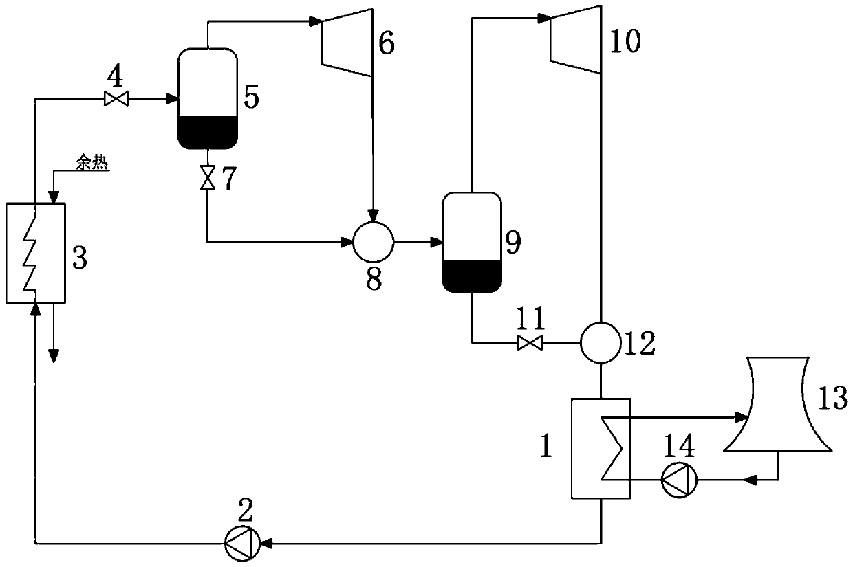
[0022] See attached figure 1 . A non-azeotropic working medium two-stage organic flash cycle system, including a condenser 1, a working medium pump 2, a heat exchanger 3, a first throttle valve 4, a high-pressure stage gas-liquid separator 5, and a high-pressure stage turbine 6 , high-pressure stage mixer 8, second throttle valve 7, low-pressure stage gas-liquid separator 9, low-pressure stage turbine 10, low-pressure stage mixer 12 and the third throttle valve 11; the thermal fluid side of the condenser 1 The outlet, the working medium pump 2 and the inlet of the cold fluid side of the heat exchanger 3 are sequentially connected through pipelines; the outlet of the cold fluid side of the heat exchanger 3, the first throttle valve 4 and the inlet of the high-pressure stage gas-liquid separator 5 Connect sequentially through pipelines; the steam outlet of the high-pressure stage gas-liquid separator 5 is connected with the inlet of the high-pressure stage turbine 6 through pip...
Embodiment 2
[0024] See attached figure 1 . A non-azeotropic working medium two-stage organic flash cycle system, including a condenser 1, a working medium pump 2, a heat exchanger 3, a first throttle valve 4, a high-pressure stage gas-liquid separator 5, and a high-pressure stage turbine 6 , high-pressure stage mixer 8, second throttle valve 7, low-pressure stage gas-liquid separator 9, low-pressure stage turbine 10, low-pressure stage mixer 12 and the third throttle valve 11; the thermal fluid side of the condenser 1 The outlet, the working medium pump 2 and the inlet of the cold fluid side of the heat exchanger 3 are sequentially connected through pipelines; the outlet of the cold fluid side of the heat exchanger 3, the first throttle valve 4 and the inlet of the high-pressure stage gas-liquid separator 5 Connect sequentially through pipelines; the steam outlet of the high-pressure stage gas-liquid separator 5 is connected with the inlet of the high-pressure stage turbine 6 through pip...
Embodiment 3
[0031] See attached figure 1 . A method for recovering heat energy of a non-azeotropic working medium two-stage organic flash cycle system, using the above-mentioned non-azeotropic working medium two-stage organic flash cycle system, including a waste heat absorption step, a heat energy utilization step and a working medium Cooling step; the step of absorbing waste heat is specifically: the working fluid comes out from the hot fluid side outlet of the condenser 1, and enters the cold fluid side inlet of the heat exchanger 3 after being pressurized by the working fluid pump 2, and the working fluid is in the heat exchanger 3 and The waste heat medium input from the hot fluid side inlet of the heat exchanger 3 and output from the hot fluid side outlet of the heat exchanger 3 is heat-exchanged; the heat energy utilization steps are as follows: the working fluid comes out from the cold fluid side outlet of the heat exchanger 3, passes through After throttling by the first throttl...
PUM
 Abstract
Description
Claims
Application Information