Heat pump drying equipment, and dehumidifying control method and dehumidifying control device thereof

A heat pump drying and equipment technology, applied in lighting and heating equipment, drying, heat pump and other directions, can solve the problems of poor dehumidification reliability, waste of energy, unfavorable energy conservation and environmental protection, etc.

Inactive Publication Date: 2020-01-14
GREE ELECTRIC APPLIANCES INC
View PDF6 Cites 3 Cited by
  • Summary
  • Abstract
  • Description
  • Claims
  • Application Information

AI Technical Summary

Problems solved by technology

In the traditional heat pump drying unit, most of them use the method of dehumidification, which loses a lot of high-grade heat energy, wastes energy, is not conducive to energy saving and environmental protection, and cannot accurately control the humidity in the drying room. Relative humidity
In the dehumidification heat pump unit, most of them adopt the closed dehumidification method. Due to the large difference in the operating conditions of the evaporator and the condenser, in the actual operation of the unit, the compression ratio is large, the exhaust temperature is high, and the heating energy efficiency ratio of the equipment is low. Poor dehumidification effect and poor dehumidification reliability

Method used


Image

  • Heat pump drying equipment, and dehumidifying control method and dehumidifying control device thereof
  • Heat pump drying equipment, and dehumidifying control method and dehumidifying control device thereof
  • Heat pump drying equipment, and dehumidifying control method and dehumidifying control device thereof

Examples


Embodiment Construction

[0063] The present invention will be further described below in conjunction with the accompanying drawings and embodiments.

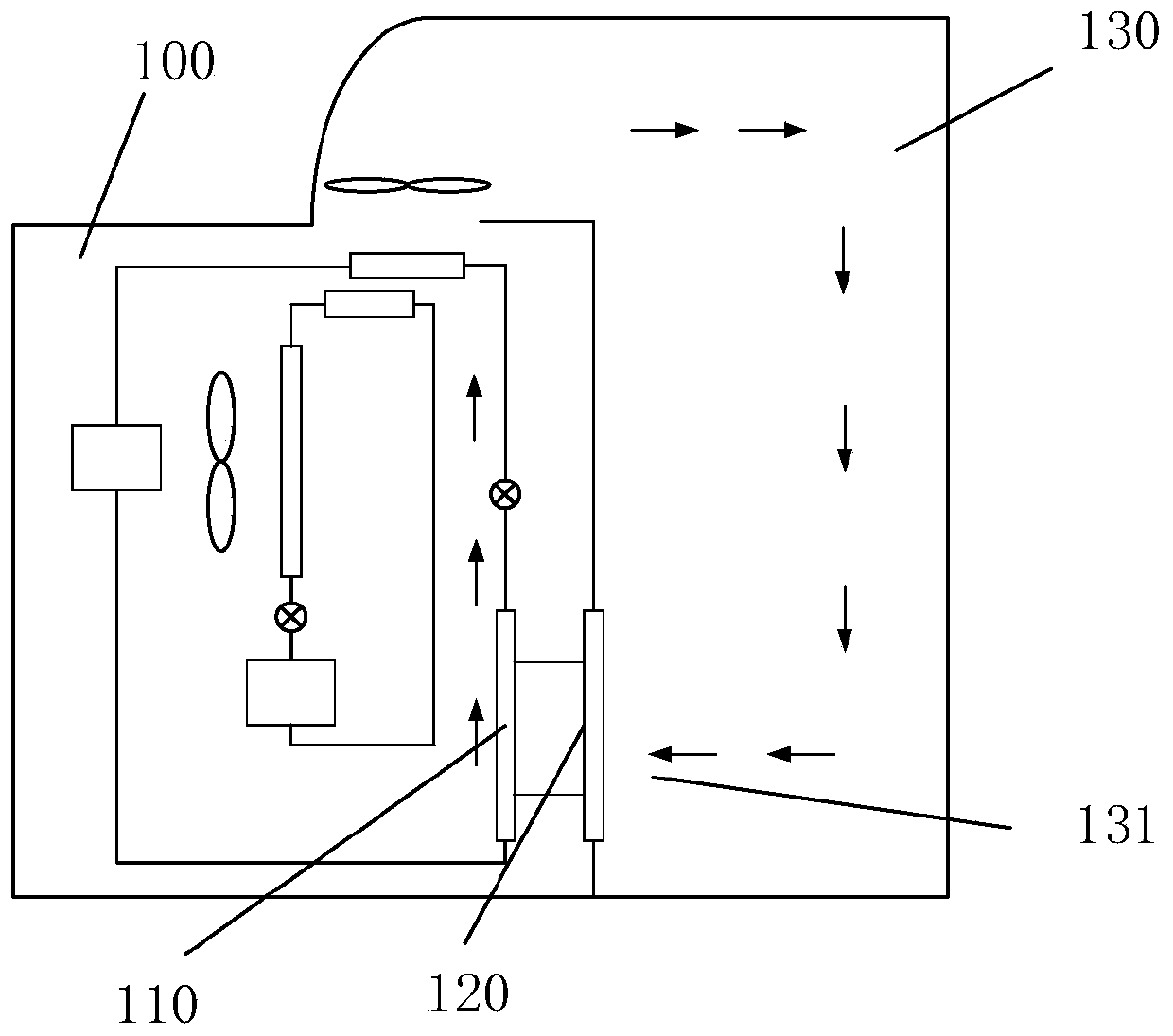
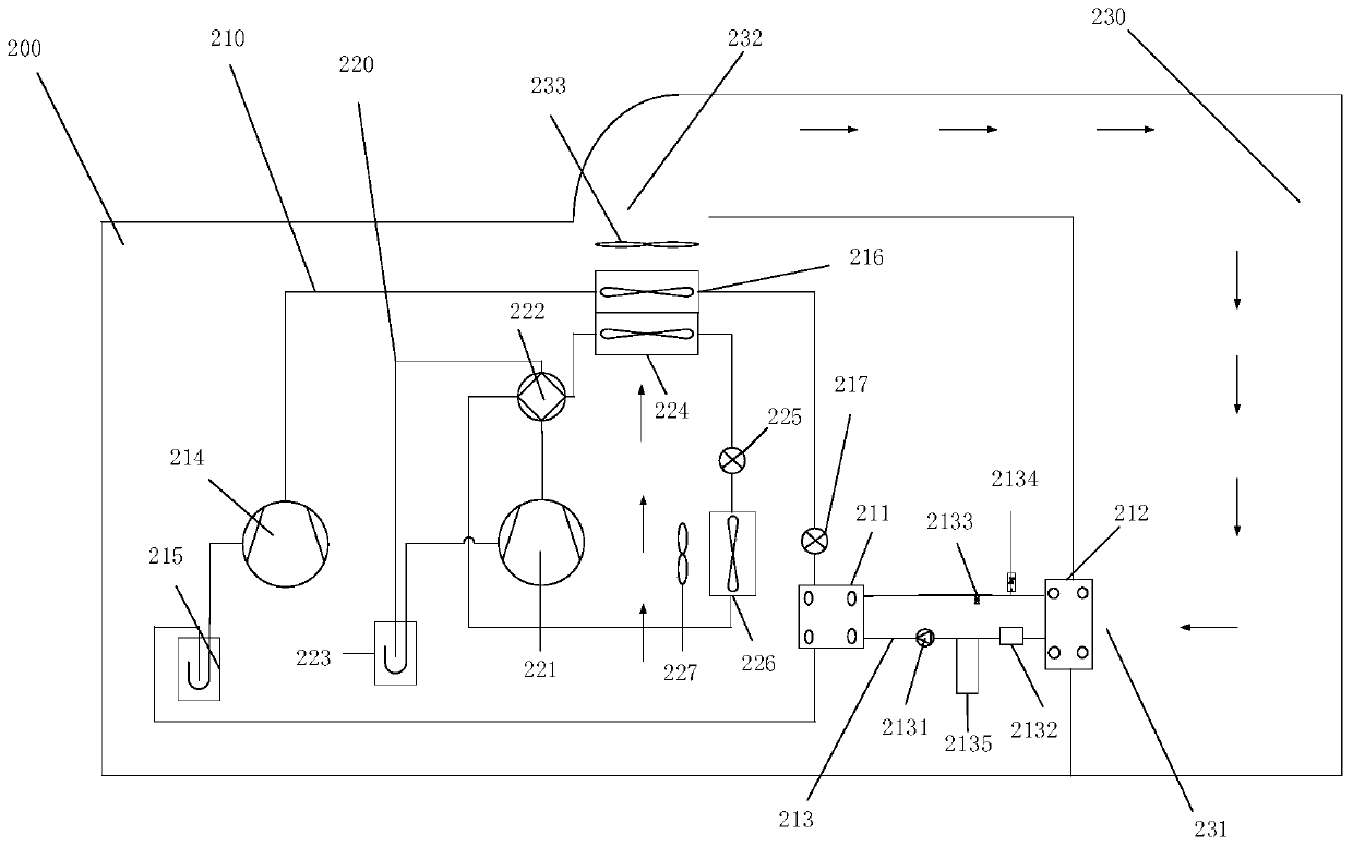
[0064] refer to figure 1 , figure 2 , it should be noted that the arrows in the figure represent the direction of air flow when the equipment is working. The embodiment of the present invention provides a heat pump drying equipment 100, including:

[0065] first evaporator 110;

[0066] A dehumidification module 120 connected to the first evaporator 110;

[0067] The dehumidification module 120 is used for condensing and dehumidifying the air flowing out through the air return port 131 of the drying room 130 .

[0068] A heat pump drying device provided in an embodiment of the present invention includes a first evaporator and a dehumidification module connected to the first evaporator. The dehumidification module is used to condense and dehumidify the air flowing out of the return air outlet of the drying room. The dehumidification module is connect...


PUM


Abstract

The invention discloses heat pump drying equipment, and a dehumidifying control method and a dehumidifying control device thereof. The drying equipment comprises a first evaporator and a dehumidifyingmodule connected with the first evaporator. The dehumidifying module is used for carrying out condensing and dehumidifying on air flowing out of an air returning opening of a drying room, the dehumidifying module exchanges heat with the first evaporator, and the dehumidifying effect of the dehumidifying module on the air can be ensured. On the original basis of the heat pump drying equipment, thedehumidifying module is added, the air in the drying room is dehumidified, the equipment is high in heat energy efficiency ratio, good in dehumidifying effect and high in dehumidifying reliability, meanwhile, the heat pump drying device can intelligently adjust the drying room humidity load and the water inlet and outlet temperature according to the current material and the drying stage where thematerial is located, and the wet load and the actual capacity are dynamically matched.

Description

technical field [0001] The invention relates to the technical field of drying equipment, in particular, to a heat pump drying equipment, a dehumidification control method and a dehumidification control device thereof. Background technique [0002] As an emerging drying method, heat pump drying has the advantages of energy saving, environmental protection, intelligent control, and good drying effect, and has been widely promoted. [0003] In the heat pump drying project, according to the different ways of processing the hot and humid air in the drying room, it can be divided into a dehumidification type heat pump and a dehumidification type heat pump. In the traditional heat pump drying unit, most of them use the method of dehumidification, which loses a lot of high-grade heat energy, wastes energy, is not conducive to energy saving and environmental protection, and cannot accurately control the humidity in the drying room. Relative humidity. In the dehumidification heat pu...

Claims


Application Information

Patent Timeline
Patent Type & Authority Applications(China)
IPC IPC(8): F26B9/02F25B41/06F25B43/00F25B30/02F26B21/04F26B21/08F25B41/30
CPCF26B9/02F25B43/00F25B30/02F26B21/04F26B21/086F25B41/31
Inventor 谷月明何建发陆飞荣郑神安张鸿宙
Owner GREE ELECTRIC APPLIANCES INC
Why Eureka
Try Eureka