
Rapid microwave imaging method

A microwave imaging, fast technology, applied in radio wave measurement system, radio wave reflection/re-radiation, using re-radiation, etc., can solve the problem of slow inversion speed

Active Publication Date: 2020-01-14
杭州泛利科技有限公司
View PDF3 Cites 3 Cited by
  • Summary
  • Abstract
  • Description
  • Claims
  • Application Information

AI Technical Summary

Problems solved by technology

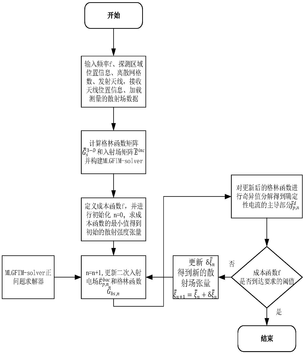
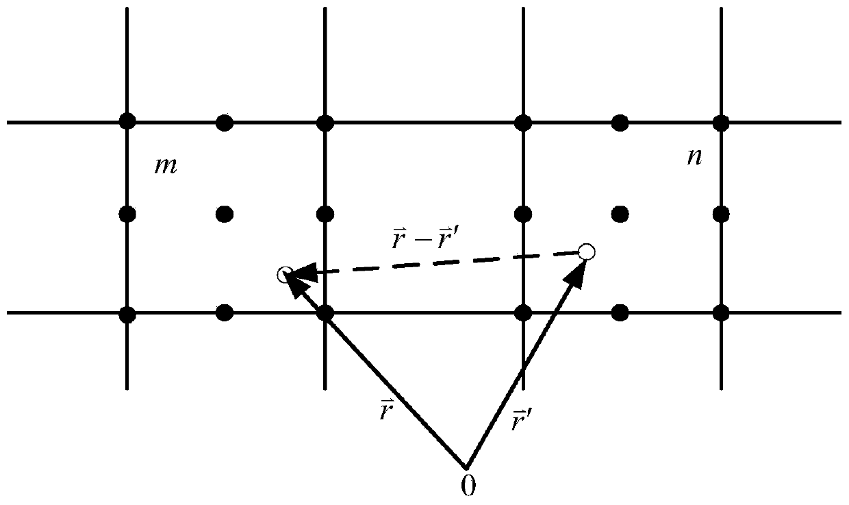
[0005] The technical problem to be solved by the present invention is the slow inversion speed of the traditional three-dimensional microwave imaging method, and a fast microwave imaging method is proposed, which uses the modified MS-DBIM based on the deformed Born approximation (DBIM) inversion algorithm On the basis of , an efficient direct problem solver is integrated. The solver uses an interpolation algorithm independent of the integral kernel, that is, the multi-layer Green's function interpolation algorithm (MLGFIM). This solver can be named MLGFIM-Solver .The advantage is that in each iteration of the DBIM algorithm, by calling this efficient direct problem solver, we can calculate the direct problem relatively quickly to improve the inversion speed

Method used


Image

  • Rapid microwave imaging method
  • Rapid microwave imaging method
  • Rapid microwave imaging method

Examples


Embodiment 1

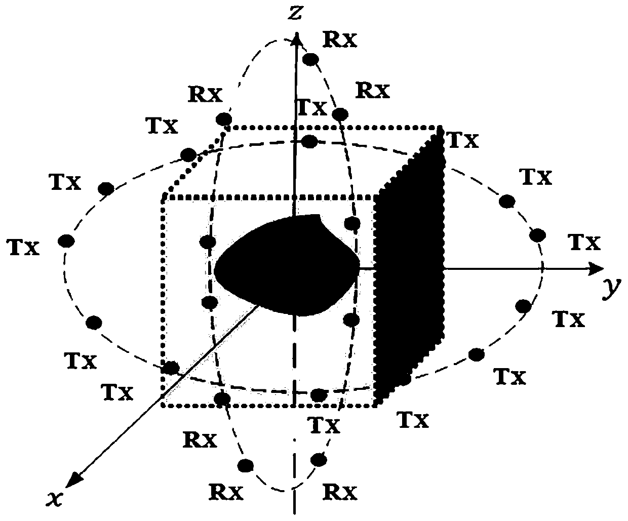
[0083] Such as Figure 4 , Example 1 is two spheres with a radius of 0.5λ, the relative permittivity of the two spheres is 1.5, and their center coordinates are (0,0.5λ,0), (0,0.5λ,0) respectively. In the iterative process of MS-DBIM-MLGFIM, the imaging area is discretized into 32×32×32 grids, and through 18 iterations, Figure 5 is the imaging result of the invented method, Figure 5 (a), (b), and (c) are cross-sectional views of the inversion results at z=0, x=0, y=-0.5λ, respectively. It can be seen that the invented inversion algorithm MS-DBIM-MLGFIM can accurately invert the positions and sizes of the two spheres, and can estimate their relative permittivity to be about 1.5.

[0084] Simulation example 2

[0085] To further validate the effectiveness of the proposed method, the method is tested with a more complex design objective. This unknown consists of two spheres and a U-shaped structure such as Figure 6 shown. The centers of the two spheres are located at (0,...


PUM


Abstract

The invention discloses a rapid microwave imaging method. In each iteration process of a DBIM algorithm, an inversion speed is improved by calling an efficient forward problem solver to calculate a forward problem. Meanwhile, in order to enable a whole inversion algorithm to stably carry out iterative inversion, a truncated singular value decomposition (TSVD) technology is adopted, and a large number of numerical tests are prevented from being used for determining regularization terms. In order to further reduce a calculated amount, in a cost function of an inversion algorithm, an incident field is used to replace a total field. Therefore, the method can achieve quick and stable inversion, and an inversion speed and quality of an image are ensured.

Description

technical field [0001] The invention belongs to the technical field of microwave imaging and provides a fast microwave imaging method. Background technique [0002] Microwave imaging technology is based on the research of microwave propagation and scattering in various complex media, and reconstructs the complex permittivity image inside the measured medium by measuring the scattered field data outside the measured medium. The measured scattering field carries a large amount of information about the scatterer. Using the prior knowledge about the scattering target, some characteristics of the scatterer itself can be extracted after appropriate mathematical processing, such as the shape of the scatterer, the dielectric constant distribution etc. Because microwave imaging can realize non-destructive detection of targets, can simultaneously perform geometric imaging and physical imaging of targets, and has high resolution, microwave imaging technology has a wide range of applic...

Claims


Application Information

Patent Timeline
Patent Type & Authority Applications(China)
IPC IPC(8): G01S13/89G01S7/41
CPCG01S7/41G01S13/89
Inventor 徐魁文刘林春赵鹏王高峰
Owner 杭州泛利科技有限公司
Learn More