Electric mechanical stretching device

A stretching device and mechanical technology, applied in the field of furniture, can solve the problems of reduced comfort, complex running track, complicated use process, etc., and achieve the effect of reducing force transmission process, simple movement track, and simple use process.

Inactive Publication Date: 2020-01-17
UE FURNITURE CO LTD
View PDF0 Cites 1 Cited by
  • Summary
  • Abstract
  • Description
  • Claims
  • Application Information

AI Technical Summary

Problems solved by technology

[0002] The electromechanical stretching device is a functional frame product that is widely used in functional sofa seats at present. Users can adjust the different states of the sofa seat according to their own needs (such as sitting and lying positions), which is comfortable and convenient; however, the existing electromechanical stretching device The device is generally complex in structure, bulky and bulky, resulting in limited functional design and waste of space in seat design, and there are many problems such as complicated use process, low fit, poor comfort, inconvenient transportation, and high cost; specifically, In other words, for example, complex and numerous rods are easy to interfere and limit the design of the seat frame’s low position and seat frame lengthening; for another example, the complex structure and running track will easily lead to complicated use process. Simultaneous opening (usually after the footrest is opened, and then the backrest is tilted), which is prone to displacement of the back cushion and seat cushion relative to the device, greatly reducing comfort and poor user experience

Method used


Image

  • Electric mechanical stretching device
  • Electric mechanical stretching device
  • Electric mechanical stretching device

Examples


specific Embodiment approach

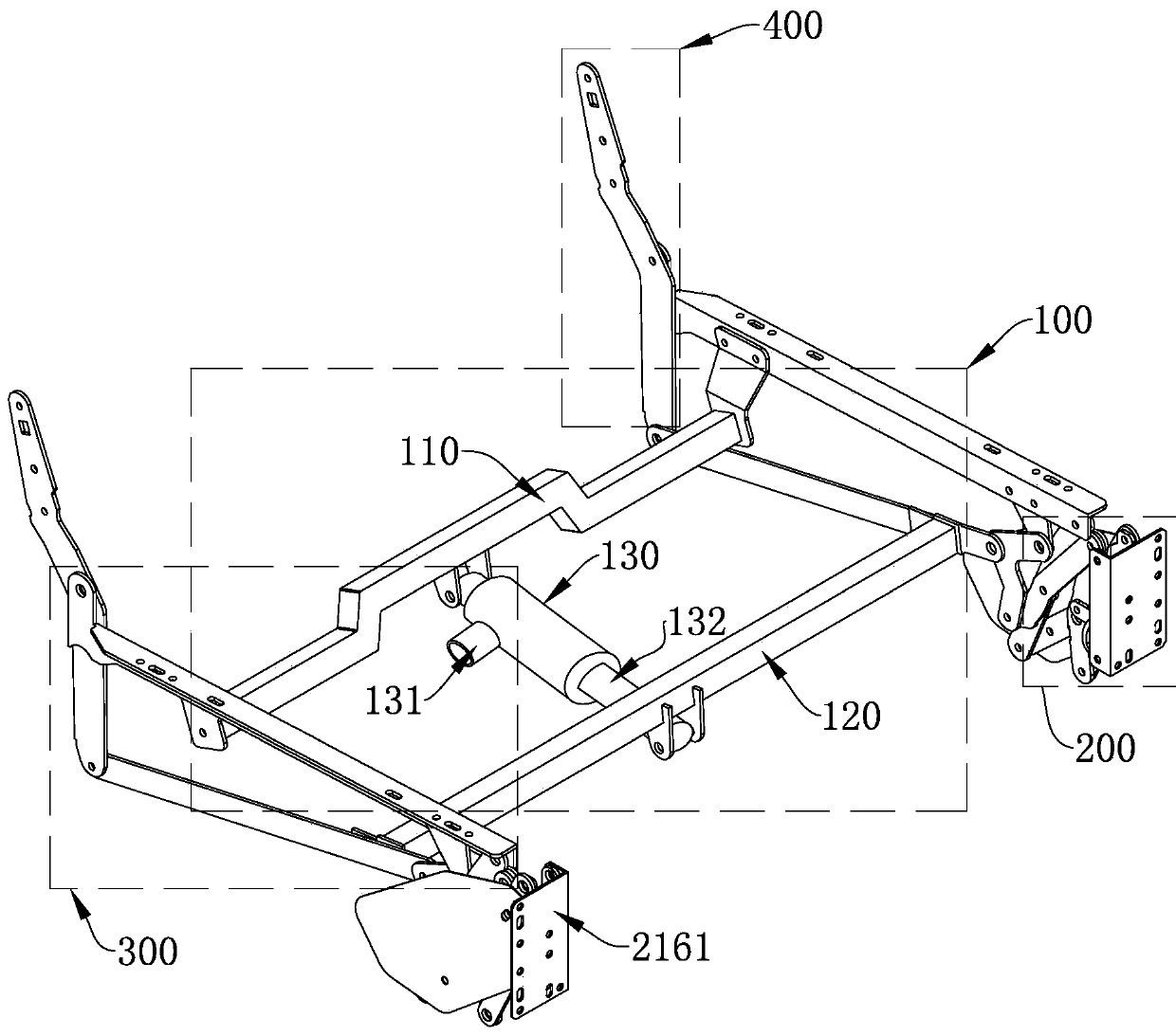
[0034] The directional words such as "front" and "rear" involved in this embodiment are described by the user's field of view after the user sits on the seat. For example, the front of the user is "front", and the legrest assembly 200 , the seat frame support assembly 300 and the backrest assembly 400 are arranged sequentially from front to back.

Embodiment

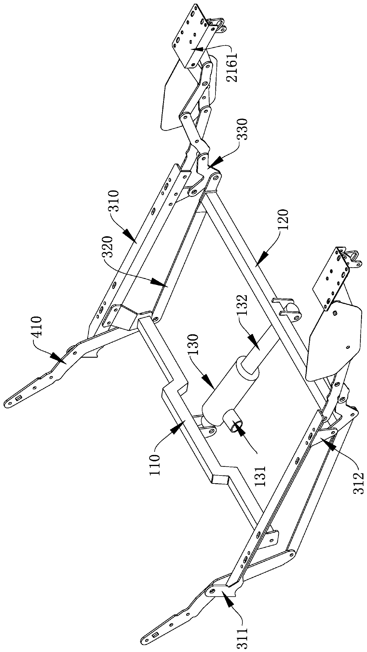
[0036] An electromechanical stretching device such as Figure 1~4 As shown, the drive assembly 100 is included, and the left and right sides of the drive assembly 100 are provided with left and right paired leg rest assemblies 200, seat frame support assemblies 300 and backrest assemblies 400, and the front and rear ends of the seat frame support assembly 300 are respectively connected to the leg rest assemblies. One end of assembly 200 is hinged to one end of backrest assembly 400 .

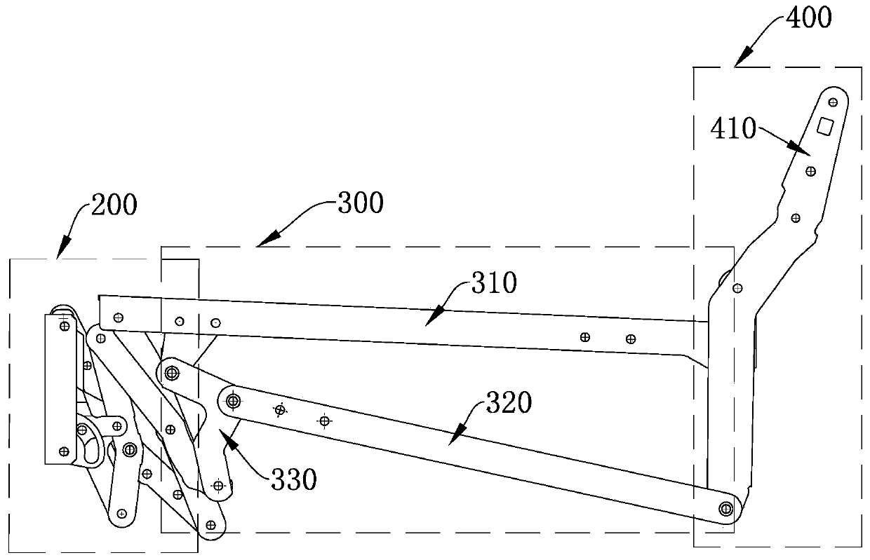
[0037] Specifically, the seat frame support assembly 300 includes a support fixed rod 310 and a support transmission rod 320 distributed up and down, the rear end of the support fixed rod 310 and the rear end of the support transmission rod 320 are hinged with the backrest assembly 400, supporting The front end of the fixed rod 310 is hinged with the leg rest assembly 200, and the front end of the supporting transmission rod 320 is hinged with a linkage rod 330, the linkage rod 330 is a crank stru...


PUM


Abstract

The invention relates to an electric mechanical stretching device that comprises a driving assembly, a leg placing assembly, a seat frame supporting assembly and a backrest assembly; the seat frame supporting assembly comprises supporting fixing rods and supporting transmission rods which are distributed up and down, the rear ends of the supporting fixing rods and the supporting transmission rodsare hinged to the backrest assembly, the front end of the supporting fixing rod is hinged to the leg placing assembly, a linkage rod is hinged to the front end of the supporting transmission rod, andthe two ends of the linkage rod are hinged to the leg placing assembly and the supporting fixing rods respectively; the driving assembly comprises a driving fixing rod with the two ends connected withthe left supporting fixing rod and the right supporting fixing rod correspondingly, a driving transmission rod with the two ends connected with the left supporting transmission rod and the right supporting transmission rod correspondingly, and a push rod motor arranged between the driving fixing rod and the driving transmission rod used for pushing the driving transmission rod to move relative tothe driving fixing rod to achieve stretching and closing of the device. Compared with the prior art, the electric mechanical stretching device has the advantages of simplified structure, conveniencein functional design of the seat, high comfort level, stability, firmness, high universality and low cost.

Description

technical field [0001] The invention relates to the technical field of furniture, in particular to an electromechanical stretching device. Background technique [0002] The electromechanical stretching device is a functional frame product that is widely used in functional sofa seats at present. Users can adjust the different states of the sofa seat according to their own needs (such as sitting and lying positions), which is comfortable and convenient; however, the existing electromechanical stretching device The device is generally complex in structure, bulky and bulky, resulting in limited functional design and waste of space in seat design, and there are many problems such as complicated use process, low fit, poor comfort, inconvenient transportation, and high cost; specifically, In other words, for example, complex and numerous rods are easy to interfere and limit the design of the seat frame’s low position and seat frame lengthening; for another example, the complex stru...

Claims


Application Information

Patent Timeline
Patent Type & Authority Applications(China)
IPC IPC(8): A47C7/50A47C7/46
CPCA47C7/46A47C7/506
Inventor 李文才施振杰李立波尚俊
Owner UE FURNITURE CO LTD
Why Eureka
Try Eureka