
Inverted cone led bracket step-by-step side push molding method

A technology of LED bracket and molding method, which is applied in the direction of molding tools, metal processing equipment, manufacturing tools, etc., to achieve the effects of avoiding interference wear and abnormal damage, high anti-aging light decay, and improving resolution

Active Publication Date: 2021-03-12
ZHONGSHAN MULINSEN ELECTRONICS CO LTD +1
View PDF7 Cites 0 Cited by
  • Summary
  • Abstract
  • Description
  • Claims
  • Application Information

AI Technical Summary

Problems solved by technology

[0003] Regardless of indoor or outdoor LED displays, industry companies are striving to pursue small, smaller, and extremely small pitches in order to achieve or consolidate their leading position in the industry. However, because the working environment of outdoor LED displays is different from indoors, the core components Compared with indoor lamp beads, "LED lamp beads" have higher quality requirements such as moisture resistance and anti-aging light decay, and have more special requirements for the structure of lamp beads, so the shape and specification of lamp beads are larger than those indoors; the current industry outdoor The specification of small-pitch lamp beads for high-end display screens is 2020, but these specifications can no longer meet the actual needs. For this reason, it is urgent for those skilled in the art to develop a method that can be processed and formed into an inverted cone LED bracket to process and form both LED brackets with smaller specifications and higher quality requirements such as moisture resistance and high anti-aging and light decay, so as to meet the production of outdoor full-color lamp beads with smaller spacing to further improve the resolution of LED displays, so that outdoor LED displays Display technology to a higher level

Method used


Image

  • Inverted cone led bracket step-by-step side push molding method
  • Inverted cone led bracket step-by-step side push molding method
  • Inverted cone led bracket step-by-step side push molding method

Examples


Embodiment Construction

[0056] The present application will be described in further detail below through specific embodiments in conjunction with the accompanying drawings.

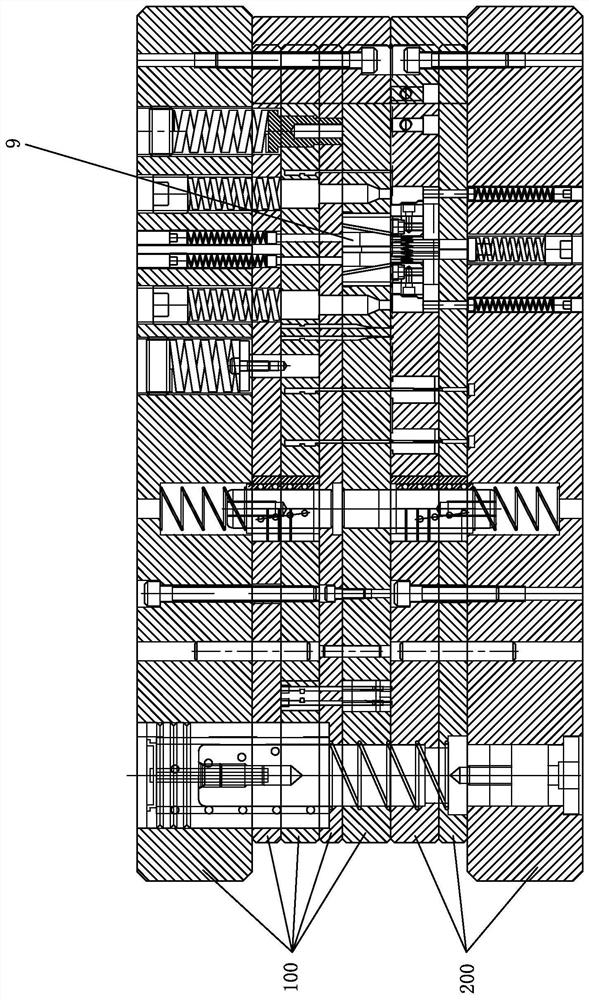
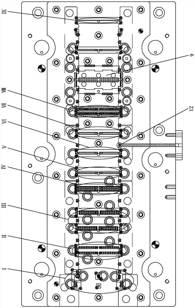
[0057] Such as Figure 1-23 As shown, the inverted cone LED bracket molding mold includes an upper die set 100 and a lower die set 200 that is compatible with the upper die set 100, and is located between the upper die set 100 and the lower die set 200 The inverted cone-type LED bracket pushes the molding structure step by step 9.

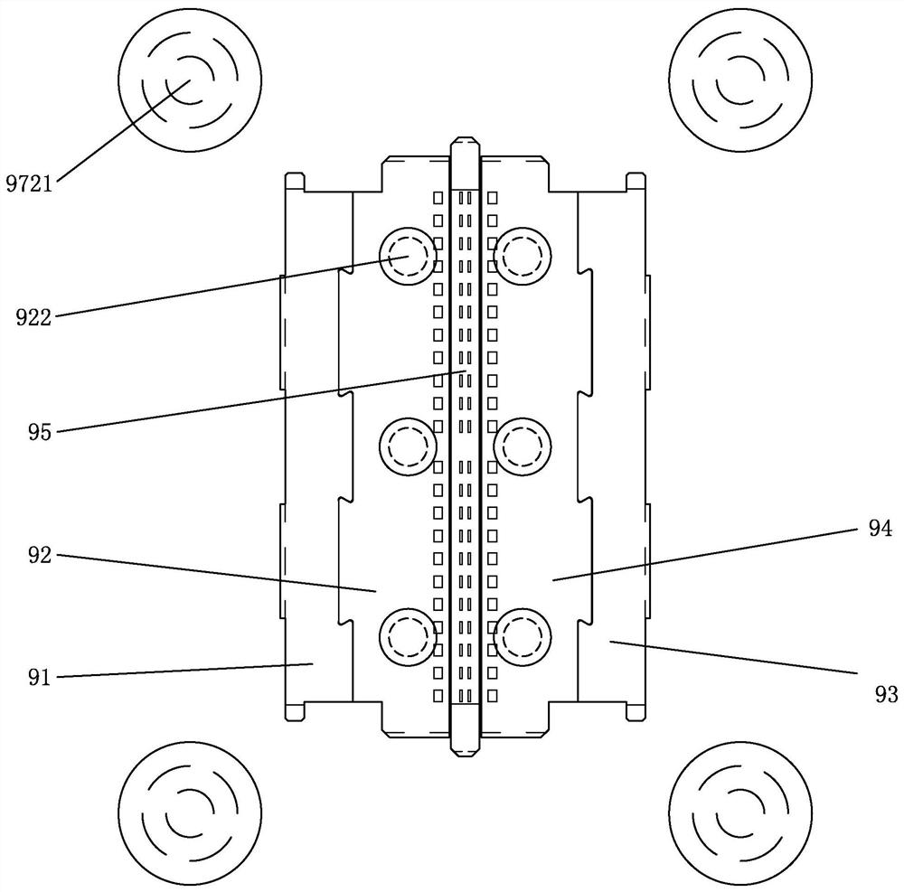
[0058] Specifically, the inverted cone-type LED bracket is pushed side by step, including an upper left slider seat 91, an upper left lower pressure group 92, an upper right slider seat 93, an upper right lower pressure group 94, an upper middle limit group 95. Lower middle upper top group 96. Left pushing group 97. Right pushing group 98. The upper left slider seat 91 is disposed on the upper die set 100 . The upper left lower pressing group 92 is arranged on the right side of the upper left slid...


PUM


Abstract

The application discloses a step-by-step side-pushing forming method for an inverted-cone LED bracket. The method comprises the following steps that S1, punching forming is conducted on a side-pushingLED bracket so that the left side of a positive-cone LED bracket is provided with a first slope tilting leftwards and the right side of the positive-cone LED bracket is provided with a second slope tilting rightwards; S2, punching cutting is conducted on the bottom of the positive-cone LED bracket so that a punched water pit is formed; S3, push-pressing forming is conducted on the first slope tilting leftwards on the left side of the positive-cone LED bracket to be the first slope tilting rightwards; and S4, push-pressing forming is conducted on the second slope tilting leftwards on the rightside of the positive-cone LED bracket to be the second slope tilting leftwards, so that the positive-cone bracket is formed to be the inverted-cone LED bracket. By means of the step-by-step side-pushing forming method, the inverted-cone LED bracket with smaller specifications and higher moisture resistance and high anti-aging light decay and other high-quality requirements can be processed and formed, so that the step-by-step side-pushing forming method can meet production of smaller-pitch outdoor full-color lamp beads so as to further improve the resolution ratio of an LED display, and the display technology of the outdoor LED display goes up a storey still higher accordingly.

Description

【Technical field】 [0001] The present application relates to the technical field of LEDs, and in particular relates to a step-by-step side-push forming method of an inverted-cone LED bracket. 【Background technique】 [0002] LED is widely used in various fields of daily life because of its environmental protection and low carbon, and with the rapid development of LED display technology, people's requirements for visual effects are getting higher and higher, and then LED display technology needs to be more high-definition, More subtle display level development. [0003] Regardless of indoor or outdoor LED displays, industry companies are striving to pursue small, smaller, and extremely small pitches in order to achieve or consolidate their leading position in the industry. However, because the working environment of outdoor LED displays is different from indoors, the core components Compared with indoor lamp beads, "LED lamp beads" have higher quality requirements such as mois...

Claims


Application Information

Patent Timeline
Patent Type & Authority Patents(China)
IPC IPC(8): B21D35/00B21D37/08
CPCB21D35/001B21D35/002B21D37/08
Inventor 林木荣陈方石红丽罗广鸿
Owner ZHONGSHAN MULINSEN ELECTRONICS CO LTD
Learn More