V-shaped sliding rail device based on ultrasonic friction reduction

An ultrasonic anti-friction and slide rail technology, which is applied in the direction of large fixed members, metal processing machinery parts, metal processing equipment, etc., can solve problems such as locking, large friction coefficient, and affecting guiding accuracy, and achieve uniform vibration synchronization and reduce friction Coefficient, the effect of reducing motion resistance

Active Publication Date: 2020-01-17
CHANGCHUN INST OF OPTICS FINE MECHANICS & PHYSICS CHINESE ACAD OF SCI
View PDF3 Cites 4 Cited by
  • Summary
  • Abstract
  • Description
  • Claims
  • Application Information

AI Technical Summary

Problems solved by technology

[0003] V-shaped guide rails are the most widely used among many sliding guide rails. The common lathe tailstock is guided by V-shaped guide rails; although the V-shaped sliding guide rail pair has good guiding accuracy, it also has a large friction coefficient and is prone to cold. For a series of problems such as welding and locking, people have come up with several methods to solve these problems:
[0004] 1. Use lubricants, but the lubricating effect of

Method used


Image

  • V-shaped sliding rail device based on ultrasonic friction reduction
  • V-shaped sliding rail device based on ultrasonic friction reduction
  • V-shaped sliding rail device based on ultrasonic friction reduction

Examples


Embodiment Construction

[0028] In order to make the object, technical solution and advantages of the present invention clearer, the present invention will be further described in detail below in conjunction with the accompanying drawings and embodiments. It should be understood that the specific embodiments described here are only used to explain the present invention, not to limit the present invention.

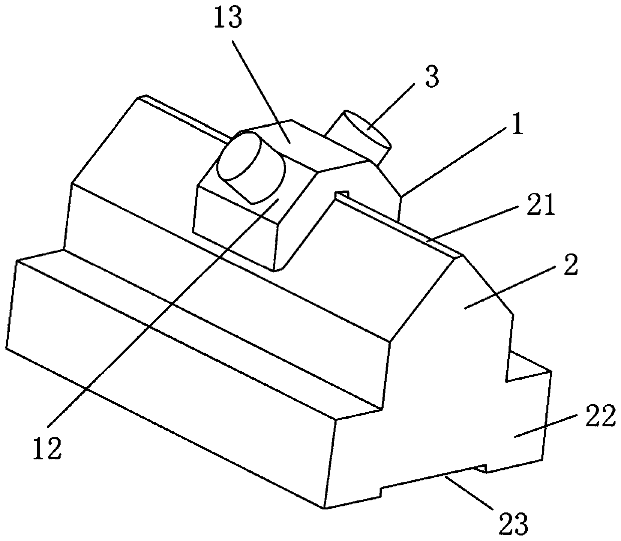
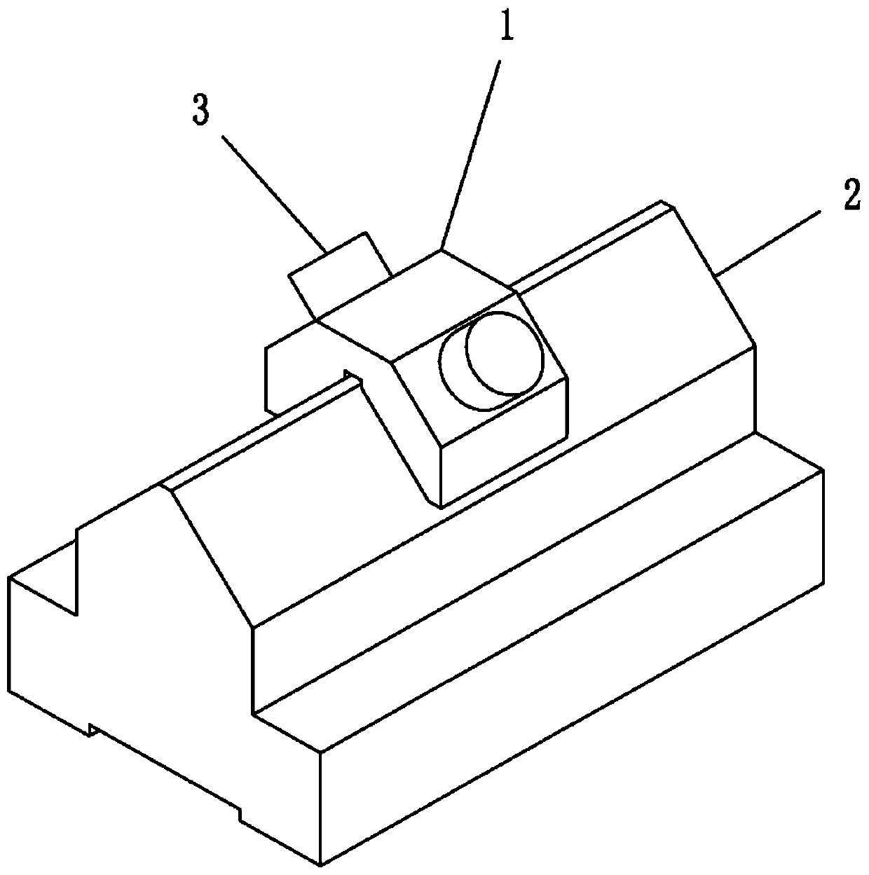
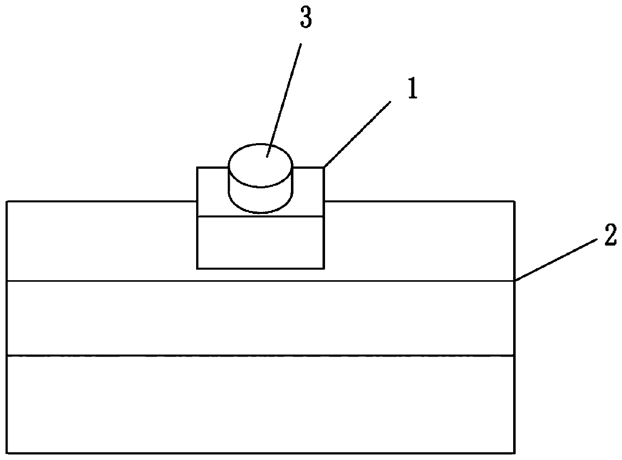
[0029] like Figure 1 to Figure 9 As shown, the present invention provides a V-shaped slide rail device based on ultrasonic friction reduction, including an upper guide rail 1, a lower guide rail 2, and two ultrasonic vibrators 3 symmetrically connected to the upper guide rail 1, and the lower guide rail 2 is in an inverted V shape. The bottom of the upper guide rail 1 is provided with a V-shaped chute 11, the upper guide rail 1 is stuck on the lower guide rail 2 through the V-shaped chute 11, and the upper guide rail 1 can slide on the lower guide rail 2.

[0030] In the present invention, two ul...


PUM


Abstract

The invention relates to the technical field of guide mechanisms, and particularly relates to a V-shaped sliding rail device based on ultrasonic friction reduction. The V-shaped sliding rail device comprises an upper guide rail, a lower guide rail and two ultrasonic vibrators symmetrically connected to the upper guide rail, wherein a V-shaped sliding groove is arranged in the bottom of the upper guide rail, the upper guide rail is clamped on the lower guide rail through the V-shaped sliding groove, and the upper guide rail can slide on the lower guide rail; the two ultrasonic vibrators are symmetrically connected to the two sides of the upper guide rail, and the two ultrasonic vibrators are electrically connected with an ultrasonic driving power supply through wires. According to the V-shaped sliding rail device based on the ultrasonic friction reduction, the ultrasonic vibrators are symmetrically connected to the two sides of the upper guide rail, the ultrasonic driving power supply drives the ultrasonic vibrators to work, the ultrasonic vibrators are symmetrical and simultaneously applies ultrasonic vibration to two sides of the upper guide rail, so that the upper guide rail is vibrated evenly and synchronously on the lower guide rail, the friction coefficient between the upper guide rail and the lower guide rail is effectively reduced, the motion resistance is reduced, so that the movement of the V-shaped sliding rail device is smoother, and the occurrence of cold welding, locking and the like is avoided.

Description

technical field [0001] The invention relates to the technical field of guide mechanisms, in particular to a V-shaped slide rail device based on ultrasonic friction reduction. Background technique [0002] The guide rail is one of the important components of the machine tool. It mainly plays the role of supporting and guiding the moving components to move along a certain track; there are many types of guide rails. Among the various types of guide rails, the sliding guide rail has simple structure, The advantages of good rigidity and high vibration resistance have been widely used in various machine tools. [0003] V-shaped guide rails are the most widely used among many sliding guide rails. The common lathe tailstock is guided by V-shaped guide rails; although the V-shaped sliding guide rail pair has good guiding accuracy, it also has a large friction coefficient and is prone to cold. For a series of problems such as welding and locking, people have come up with several meth...

Claims


Application Information

Patent Timeline
IPC IPC(8): B23Q1/01
CPCB23Q1/017
Inventor 姚雪峰唐玉国齐向东崔继承糜小涛王明佳葛明达
Owner CHANGCHUN INST OF OPTICS FINE MECHANICS & PHYSICS CHINESE ACAD OF SCI
Why Eureka
Try Eureka