
A Method of Obstacle Avoidance Based on Probing Perception of Manipulator

A robotic arm and obstacle avoidance technology, applied in the field of industrial robot path planning, can solve problems such as unfavorable automated production, and achieve the effect of improving the scope of application and improving work efficiency

Active Publication Date: 2020-12-01
HEBEI UNIV OF TECH
View PDF6 Cites 0 Cited by
  • Summary
  • Abstract
  • Description
  • Claims
  • Application Information

AI Technical Summary

Problems solved by technology

The common point of these studies is that after a collision is detected, the task performed by the robotic arm will be terminated. After the operator leaves and safety is ensured, the robotic arm will be re-planned to continue working, which is not conducive to efficient automated production.

Method used


Image

  • A Method of Obstacle Avoidance Based on Probing Perception of Manipulator
  • A Method of Obstacle Avoidance Based on Probing Perception of Manipulator
  • A Method of Obstacle Avoidance Based on Probing Perception of Manipulator

Examples


Embodiment

[0043] The present invention is verified below with a specific embodiment, the specific embodiment selects the UR robotic arm as the object, but the implementation object is not limited thereto.

[0044] Step 1: Input initial joint angle, target position, desired trajectory;

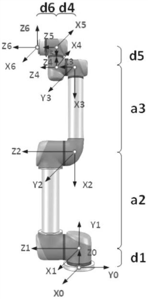
[0045] Step 2: Establish the kinematics model of the robotic arm. This paper takes the UR5 robot as the main research object. UR5 is a tandem robot with 6 rotating joints. In order to clearly show the pose relationship between the connecting rods of the robot, the D-H coordinate transformation method can be used for modeling. The D-H coordinate system of the robot is as follows: figure 1 shown. figure 1 In , the number of joints starts from 0, that is, joint 0 is the base. x i 、y i ,z i are the coordinate system of joint i in space.

[0046] The connecting rod parameters of industrial robots are divided into the geometric parameters of the connecting rod and the relationship parameters of the con...

Embodiment 2

[0074] The research object and process of this embodiment are the same as those of Embodiment 1, the difference is that this application adopts the external observer modeling method for collision detection,

[0075] Establish the current-based external force observer model of the manipulator. The joint output torque of the manipulator is determined by the motor torque τ m , external moment τ ext and the interference term ρ consists of three parts:

[0076] τ all =τ m +τ ext +ρ (7)

[0077] where the disturbance term ρ includes the friction torque τ f and the flexible element bears torque τ fle , the joint flexibility mainly comes from the harmonic reducer, which reduces the joint stiffness and has a flexible feature.

[0078] Given the expected trajectory, the estimated torque of the dynamic system is calculated according to the expected angle, expected angular velocity, and expected angular acceleration of each joint of the robot. τ m Indicates the torque required t...


PUM


Abstract

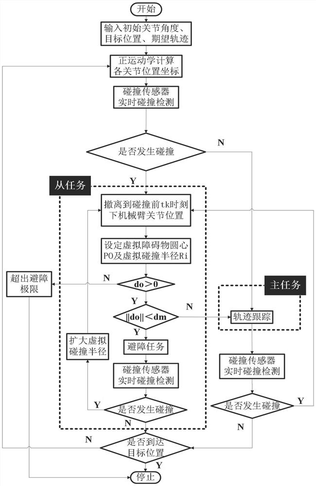
The invention discloses an obstacle avoiding method with a mechanical arm probing and perceiving function. The obstacle avoiding method comprises the following steps that the initial joint angle, target position and expected track of a mechanical arm are set; a kinematic model of the mechanical arm is established; whether the mechanical arm collides or not is detected in real time, and if the mechanical arm does not collide, a track tracking master task is executed, the mechanical arm tracks the tail end track all the time, obstacle avoiding is not considered, and the mechanical arm stops moving after reaching a target point; and if the mechanical arm collides, an obstacle avoiding motion slave task is executed, the mechanical arm is controlled to return according to an original route andmove to the state at previous any tk moment of the mechanical arm, and therefore the mechanical arm is separated from a colliding area and cannot continue to collide, and then an obstacle avoiding strategy for probing and perceiving is executed. According to the method, whether the mechanical arm collides or not is acquired in real time, then a corresponding virtual colliding space is built according to the colliding position, probing and perceiving obstacle avoiding is executed, and the work efficiency is improved.

Description

technical field [0001] The invention belongs to the field of industrial robot path planning, and specifically relates to an obstacle avoidance method based on the detection and perception of a mechanical arm. The obstacle avoidance method performs real-time collision detection, effectively plans obstacle avoidance for obstacles, and realizes obstacle avoidance under non-visual conditions. reaction. Background technique [0002] With the gradual expansion of the application of robotic arms in various fields, how to ensure the safety of the robotic arm body and objects in the environment is one of the key research issues in the face of complex task requirements and unknown operating environments. When the end of the manipulator encounters an obstacle on the task trajectory, the traditional collision detection algorithms are mostly based on external sensors, which not only increases the cost of the manipulator and the complexity of the control system, but also increases the cos...

Claims


Application Information

Patent Timeline
Patent Type & Authority Patents(China)
IPC IPC(8): B25J9/16
CPCB25J9/1605B25J9/1666B25J9/1694
Inventor 张建华张垚楠赵岩李辉李进姜旭
Owner HEBEI UNIV OF TECH
Learn More