A kind of reinforced pellet and preparation method thereof
A technology of pellets and cast steel pellets, which is applied in the field of products that use jumping sputtering equipment to coat the surface of pellets, and can solve problems such as poor toughness, easy breakage, and fragility
- Summary
- Abstract
- Description
- Claims
- Application Information
AI Technical Summary
Problems solved by technology
Method used
Image
Examples
Embodiment 1
[0037] The powder particles used in this embodiment are spherical cast iron pellets with a particle diameter of 3 mm, and the target material is tungsten carbide alloy.
[0038] The specific process is:
[0039] (1) Powder placement and target installation
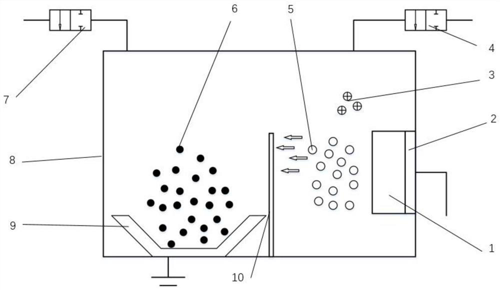
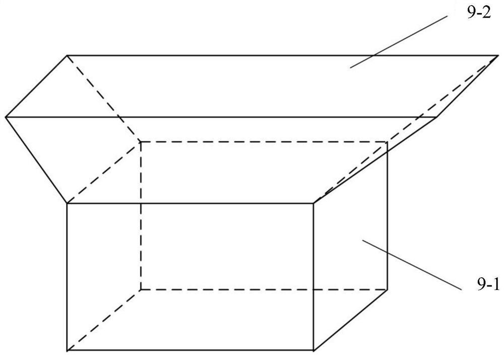
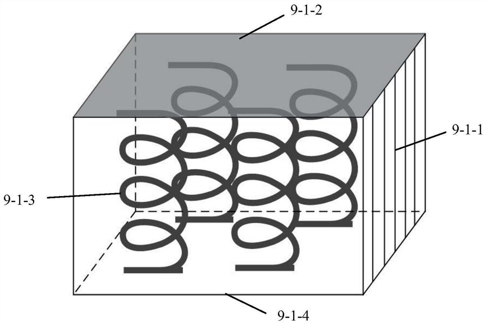
[0040] Place the cast iron pellets to be sputtered on the sample stage, and place a baffle on the sample stage. Install the tungsten carbide target on the target position, and close the vacuum chamber door.
[0041] (2) vacuuming
[0042] Turn on the mechanical pump to evacuate the vacuum chamber to below 5Pa, turn on the molecular pump in the vacuum pumping device, and evacuate the vacuum chamber to 2.0×10 -3 Pa.
[0043] (3) Pre-sputtering target
[0044]Pour argon gas into the vacuum chamber until the air pressure in the vacuum chamber is maintained at 0.5Pa, turn on the target power, control the sputtering voltage to about 300V, the sputtering current to about 0.8A, and pre-sputter the target for 15 minutes.
[0...
Embodiment 2
[0053] The powder particles used in this embodiment are spherical cast steel shots with a particle diameter of about 1 mm, and the target material is titanium nitride alloy.
[0054] The specific process is:
[0055] (1) Powder placement and target installation
[0056] Place the cast iron pellets to be sputtered on the sample stage, and place a baffle on the sample stage. Install the tungsten carbide target on the target position, and close the vacuum chamber door.
[0057] (2) vacuuming
[0058] Turn on the mechanical pump to evacuate the vacuum chamber to 3Pa, turn on the molecular pump in the vacuum pumping device, and evacuate the vacuum chamber to 2.0×10 -3 Pa.
[0059] (3) Pre-sputtering target
[0060] Pour argon gas into the vacuum chamber until the air pressure in the vacuum chamber is maintained at 0.5 Pa, turn on the target power, control the sputtering voltage to about 350V, and the sputtering current to about 0.7A, and pre-sputter the target for 15 minutes. ...
Embodiment 3
[0070] The powder particles used in this embodiment are spherical cast steel shots with a particle diameter of about 1.5 mm, and the target materials are tantalum carbide and titanium nitride alloys. Two layers of films were plated respectively, both of which were 300nm thick.
[0071] The hardness of the shot increased from HV565 before coating to HV1220.
PUM
| Property | Measurement | Unit |
|---|---|---|
| particle diameter | aaaaa | aaaaa |
| thickness | aaaaa | aaaaa |
| thickness | aaaaa | aaaaa |
Abstract
Description
Claims
Application Information
 - R&D
- Intellectual Property
- Life Sciences
- Materials
- Tech Scout
- Unparalleled Data Quality
- Higher Quality Content
- 60% Fewer Hallucinations
Browse by: Latest US Patents, China's latest patents, Technical Efficacy Thesaurus, Application Domain, Technology Topic, Popular Technical Reports.
© 2025 PatSnap. All rights reserved.Legal|Privacy policy|Modern Slavery Act Transparency Statement|Sitemap|About US| Contact US: help@patsnap.com


