Electric pole pit groove digging device

A technology for excavating devices and pits, which is applied to earth movers/shovels, construction, etc. It can solve the problems of slow construction efficiency, affecting the quality of planting poles, time-consuming and labor-intensive problems, and achieves easy depth of pits and high construction efficiency. Stable and consistent effect

Inactive Publication Date: 2020-01-17
STATE GRID CORP OF CHINA +1
View PDF5 Cites 2 Cited by
  • Summary
  • Abstract
  • Description
  • Claims
  • Application Information

AI Technical Summary

Problems solved by technology

[0003] At present, in the construction of the power grid, erecting transmission lines in the air using iron towers and poles is the main transmission method. The poles need to be planted on the ground. The depth of the working pit is difficult to ensure consistency, which affects the quality of the planted poles, which in turn affects the orientation and stability of the transmission line

Method used


Image

  • Electric pole pit groove digging device
  • Electric pole pit groove digging device
  • Electric pole pit groove digging device

Examples


Embodiment 1

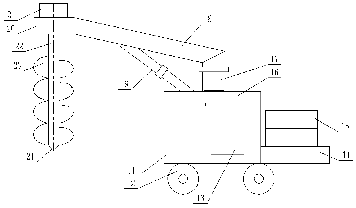
[0037] as attached figure 1 with 7 shown;

[0038] An electric pole pit digging device, comprising a vehicle frame 11, a turntable 16 rotatably connected to the vehicle frame 11, a lifting mechanism connected to the turntable 16, an excavating knife assembly connected to the lifting mechanism for digging pits, a fixed A counterweight assembly arranged at the rear of the vehicle frame 11 to balance the weight of the lifting mechanism and a running mechanism arranged at the bottom of the vehicle frame 11 .

[0039] Further, the lifting mechanism includes a fixed column 17 fixedly connected to the turntable 16, a boom 18 whose lower end is hinged on the fixed column 17, a telescopic cylinder 19 whose two ends are respectively hinged to the middle of the turntable 16 and the boom 18, and fixedly connected Horizontal mount 20 at the end of boom 18 .

[0040] Further, a central hole is provided in the middle of the turntable 16, and a center column 30 fixed on the frame 11 is arr...

Embodiment 2

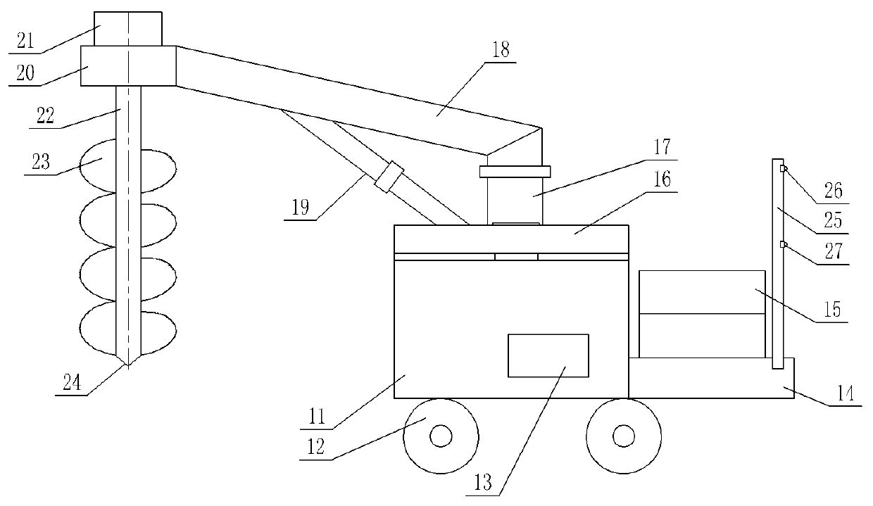
[0048] as attached figure 2 and 7 shown;

[0049] On the basis of the first embodiment, further, an alignment rod is fixedly installed on the counterweight platform 14 .

[0050] The alignment rod includes a vertical rod body 25 whose lower end is fixed on the counterweight platform 14 and a first position sensor 26 and a second position sensor 27 fixedly arranged on the vertical rod body 25 at intervals;

[0051] The detection directions of the first position sensor 26 and the second position sensor 27 are the same, and are used to detect the position of the electric pole at the front or the rear.

[0052] This embodiment realizes automatic mechanical excavation of pole-loading pits, saving time and effort, high construction efficiency, and high stability and consistency of planting poles. Position sensors are used to align the front and rear poles to ensure that the poles are planted on a straight line, thereby improving the direction of the transmission line. Accuracy a...

Embodiment 3

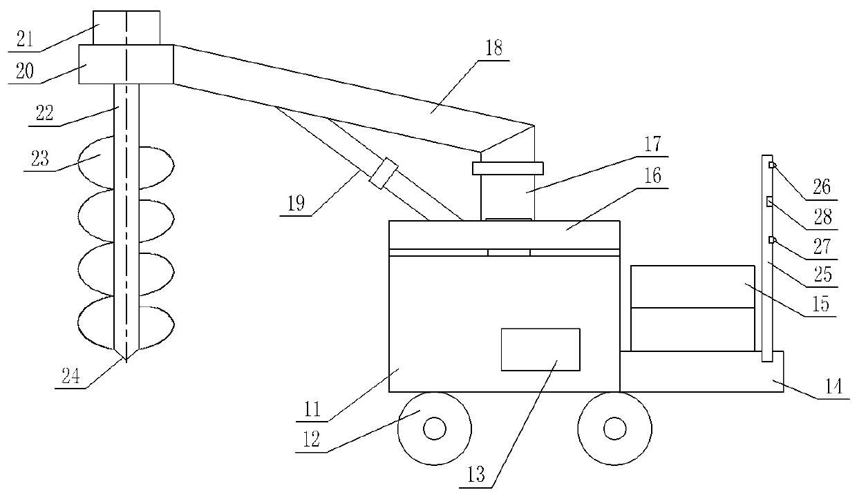
[0054] as attached image 3 , 6 and 7 as shown;

[0055] On the basis of the second embodiment, further, the vertical rod body 25 is also fixedly provided with an infrared distance sensor 28, the infrared light emission direction of the infrared distance sensor 28 is the same as the detection direction of the first position sensor 26, for Measure the separation distance from the front or rear poles.

[0056] Realize mechanical automatic digging of pole pits, saving time and labor, high construction efficiency, high stability and consistency of planting poles, using position sensors to align front and rear poles to ensure that poles are planted in a straight line, and measuring and adjusting electric poles through infrared distance sensors The distance between the poles can be adjusted to improve the direction accuracy of the transmission line and ensure the stability of the transmission line operation.


PUM


Abstract

The invention discloses an electric pole pit groove digging device. The electric pole pit groove digging device comprises a frame, a rotating disc rotatably connected to the frame, a lifting mechanismconnected to the rotating disc, a digging knife assembly connected to the lifting mechanism for digging a pit groove, a counterweight assembly fixedly arranged at the rear portion of the frame and used for balancing the weight of the lifting mechanism, and a travelling mechanism arranged below the frame. According to the electric pole pit groove digging device, a pole carrying pit is excavated through mechanical automation, time and labor are saved, the construction efficiency is high, the depth of the pit groove is convenient to control, the stability consistence of carried poles is high, aposition sensor is used for aligning the front electric pole and the rear electric pole, the carried poles are guaranteed to be in a straight line, and the interval distance among the electric poles is measured and adjusted through an infrared distance sensor, so that the direction accuracy of a power transmission line is improved, and the running stability of the power transmission line is guaranteed.

Description

technical field [0001] The invention relates to the technical field of power distribution line construction equipment, in particular to an electric pole pit excavation device. Background technique [0002] Electricity is an energy source powered by electrical energy. The primary energy in nature is converted into electricity through mechanical energy devices, and then the electricity is supplied to various users through power transmission, transformation and distribution. The transmission of electric energy, together with transformation, distribution and consumption, constitutes the overall function of the power system. Through power transmission, power plants and load centers that are far apart (up to thousands of kilometers) are connected, so that the development and utilization of electric energy transcends geographical restrictions. Compared with the transmission of other energy sources (such as coal transportation, oil transportation, etc.), power transmission has sma...

Claims


Application Information

Patent Timeline
Patent Type & Authority Applications(China)
IPC IPC(8): E02F5/20
CPCE02F5/20
Inventor 安英娟王立军王潇张磐戚惠英王千业赵洪波师进冲
Owner STATE GRID CORP OF CHINA
Why Eureka
Try Eureka