Portable drilling tool hydraulic clamp

A technology of hydraulic tongs and drilling tools, applied in the field of hydraulic tongs of drilling tools, can solve the problems of friction plate wear, many power transmission moving processes, and high maintenance requirements, and achieve the effects of small power transmission loss, stable and effective rotation, and simple overall structure.

Pending Publication Date: 2020-01-17
苏州海德石油工具有限公司
View PDF0 Cites 3 Cited by
  • Summary
  • Abstract
  • Description
  • Claims
  • Application Information

AI Technical Summary

Problems solved by technology

[0003] 1. The weight of the liquid and gas tongs is as high as 2500 kg, and it is suspended on the small beam of the derrick with limited load, which has certain safety risks;
[0004] 2. To adjust the height up and down, that is, to lift up and down, adopt the manual chain hoist method, which is slow, poor in stability and accuracy;
[0005] 3. The structure of the clamp body is complex, coupled with the cross-operation of the operators, the ability to adapt to the environment is poor, and the failure rate is high, which affects the production efficiency;
[0006] 4. There are many dynamic processes in power transmission, large kinetic energy loss, and due to component wear and pollution, especially the unstable air pressure of the pneumatic clutch, wear and tear of the friction plate, and the rated output torque value cannot be reached;
[0007] 5. Due to the very harsh operating environment for making up and breaking out of drilling tools, there is no protection against mud splashing facilities, the efficiency of drilling tool cohesion and clamping is low, slipping and idling, and scratching damages drilling tools and jaws;
[0008] 6. High manufacturing, repair and maintenance costs
[0009] It can be seen that the existing hydraulic tongs are not only complex in structure, high in maintenance requirements, prone to failure, but also high in manufacturing cost, large in size and high in weight.

Method used


Image

  • Portable drilling tool hydraulic clamp
  • Portable drilling tool hydraulic clamp
  • Portable drilling tool hydraulic clamp

Examples


Embodiment Construction

[0062] The preferred embodiments of the present invention will be described in detail below in conjunction with the accompanying drawings.

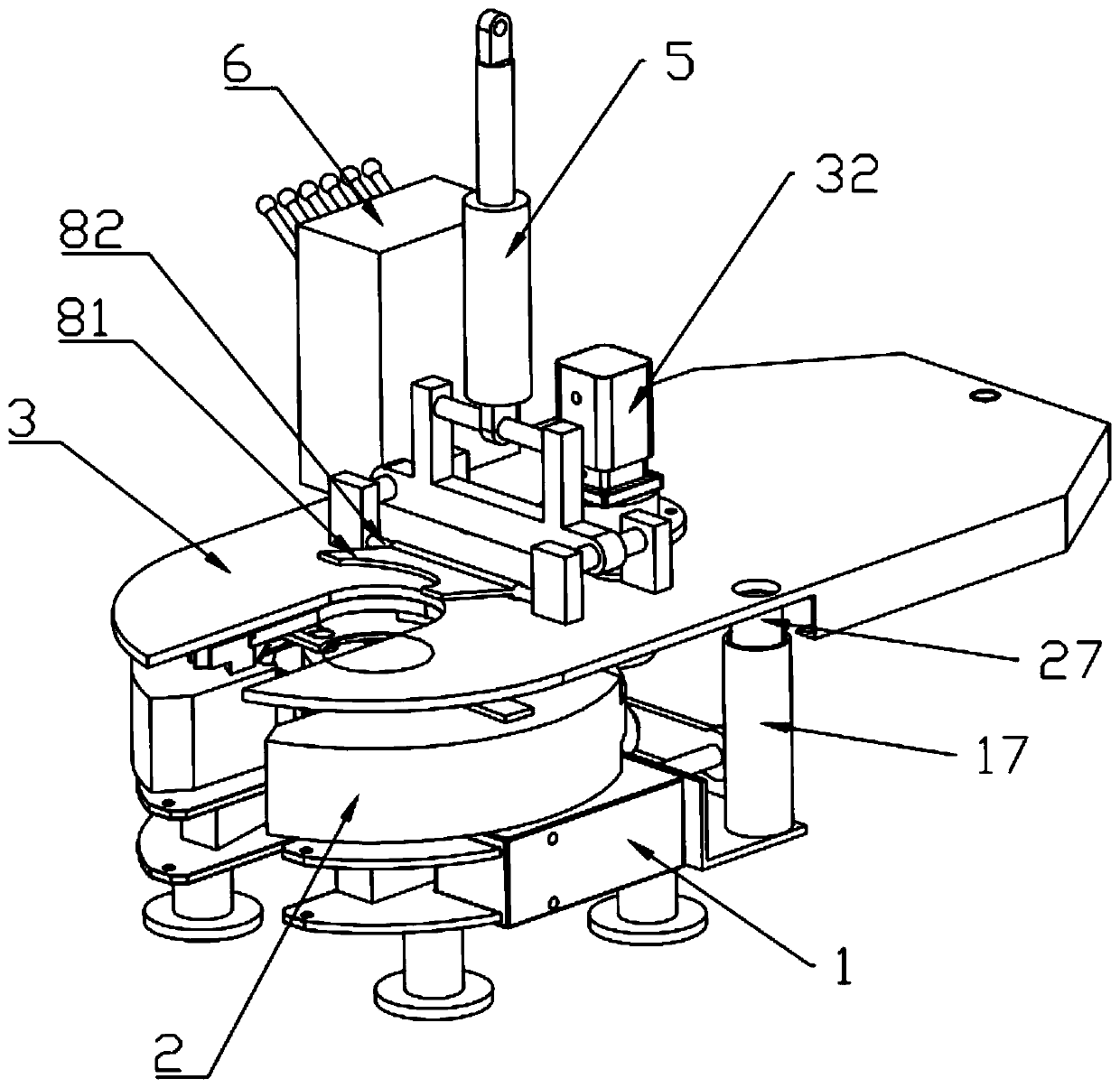
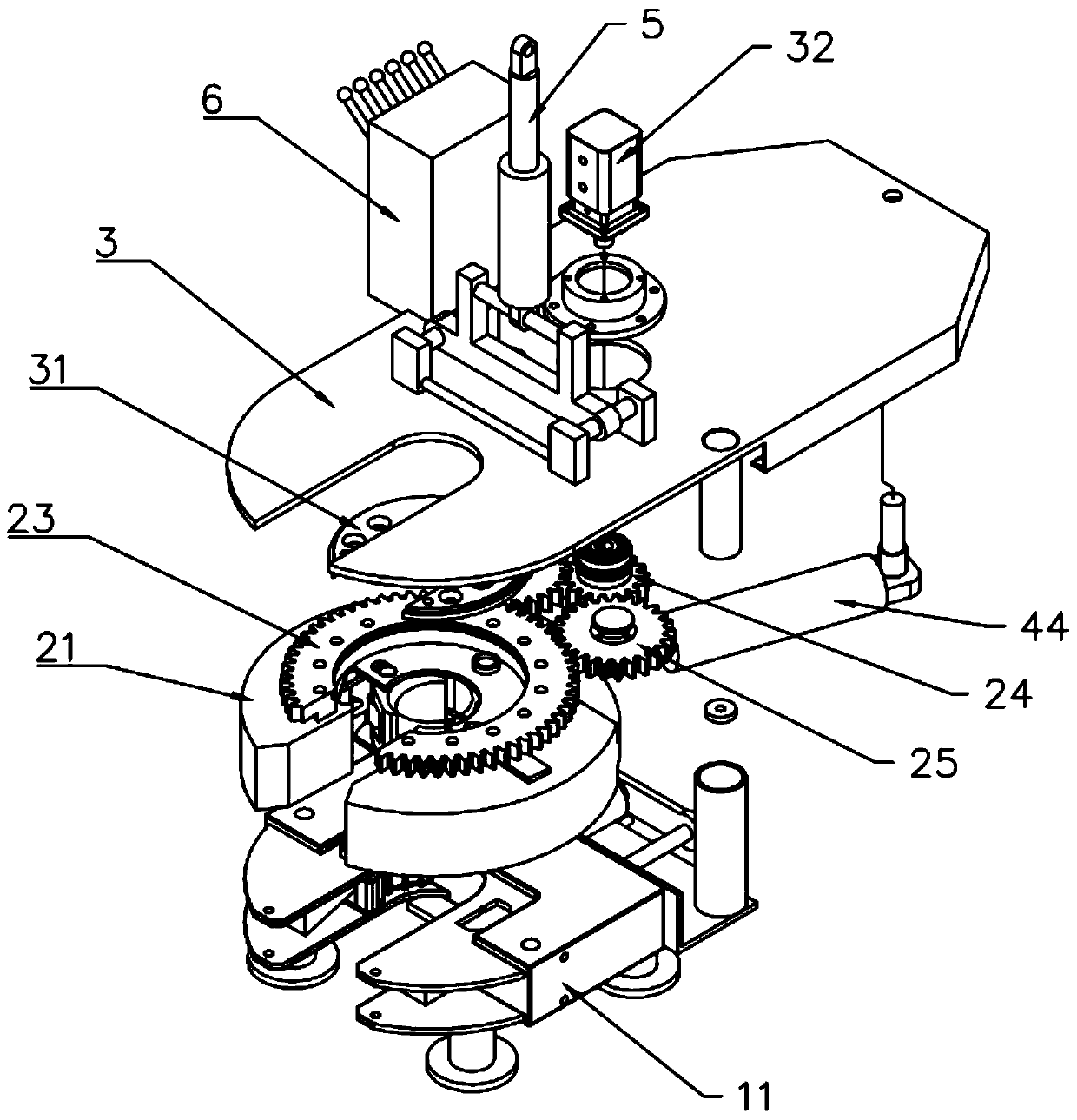
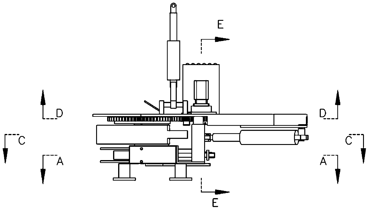
[0063] refer to Figure 1-7 , is a preferred embodiment of a portable hydraulic tong for drilling tools according to the present invention, mainly including: a lower tong body 1, an upper tong body 2, an upper plate 3 and other components.

[0064]Wherein, the lower pliers body 1 has a lower pliers body bracket 11 with a front opening, and the front opening is preferably square. Two anticline jaw plates 12 are arranged symmetrically on the left and right sides of the opening end of the lower caliper body support 11, and a wedge-shaped plate 13 is respectively arranged on the outside of the two anticline jaw plates 12. body clamping oil cylinder 16 and synchronous pull plate 15, two synchronous pull rods 14 are arranged on the left and right sides of the lower clamp body support, and the front ends of the two synchronous pull rods 14 are ...


PUM


Abstract

The invention discloses a portable drilling tool hydraulic clamp. The portable drilling tool hydraulic clamp comprises a lower clamp body, an upper clamp body and an upper plate, wherein the lower clamp body is provided with a lower clamp body bracket, back inclined jaw plates, a wedge-shaped plate, a lower clamp body clamping oil cylinder, a synchronous pull rod and a synchronous pull plate; thelower clamp body clamping oil cylinder drives the wedge-shaped plate to move through the synchronous pull plate and the synchronous pull rod, so that the clamping action of the two back inclined jaw plates on a drilling tool is realized; the upper clamp body is provided with an upper clamp body bracket, an inner groove, a slope plate, jaw plates, a notch gear and a motor gear; a gear sliding plateis fixed on the upper plate; a hydraulic motor drives the notch gear to rotate through the motor gear, so that the slope plate of the jaw plates in the inner groove is realized, and the rotation of the upper clamp body is realized while the drilling tool is tightly held. According to the portable drilling tool hydraulic clamp, the lower clamp body is large in drilling tool clamping torque and isnot easy to slip; the upper clamp body adopts a hydraulic holding clamping mode, so that the clamping torque is large, the fixing performance is good, and the upper clamp body is guaranteed to rotatestably and effectively; meanwhile, the portable drilling tool hydraulic clamp is practical, durable and simple and convenient to operate, and the manufacturing and maintenance cost is reduced.

Description

technical field [0001] The invention relates to a drilling tool hydraulic tong, in particular to a portable drilling tool hydraulic tong, which is mainly used for oil drilling operations. Background technique [0002] In drilling work, it is often necessary to clamp the drill pipe by the power tongs to realize the tightening and loosening of the drill pipe. However, the current general-purpose power tongs are the hydraulic tongs developed and produced in 1979, which have the following defects: [0003] 1. The weight of the liquid and gas tongs is as high as 2500 kg, and it is suspended on the small beam of the derrick with limited load, which has certain safety risks; [0004] 2. To adjust the height up and down, that is, to lift up and down, adopt the manual chain hoist method, the speed is slow, the stability and accuracy are poor; [0005] 3. The structure of the clamp body is complex, coupled with the cross-operation of the operators, the ability to adapt to the enviro...

Claims


Application Information

Patent Timeline
Patent Type & Authority Applications(China)
IPC IPC(8): E21B19/16
CPCE21B19/163E21B19/164
Inventor 王维桢艾波郭召勇王皖苏卫国王华
Owner 苏州海德石油工具有限公司
Why Eureka
Try Eureka