
Bending element system used for continuously testing wave velocity of soft soil in situ

A bending element and wave velocity technology, applied in the field of soil in-situ testing, can solve problems such as inability to reflect complex soil properties, inability to measure wave velocity, and inability to measure wave velocity rapidly and continuously, achieving the effect of smooth testing process and improved testing efficiency.

Pending Publication Date: 2020-01-17
TONGJI UNIV
View PDF2 Cites 2 Cited by
  • Summary
  • Abstract
  • Description
  • Claims
  • Application Information

AI Technical Summary

Problems solved by technology

For the application of this sensor in in-situ testing, Chinese patent CN101413823A discloses a portable piezoelectric ceramic bending element soil shear wave velocity testing device for testing surface soil wave velocity, however, this testing device can only be used for The wave velocity test of the ground surface or shallow soil layer soil cannot measure the wave velocity of a certain depth of soil, so the application is limited; Chinese patent CN102998368A discloses a penetrating type for in-situ shear wave velocity test of soft soil detector, but its probe structure is easily damaged when it encounters a hard soil layer, so it is not suitable for testing the wave velocity of deep soil
These devices require manual data processing, and the distance between measuring points is about 1m, which cannot realize the function of rapid and continuous measurement of wave velocity, nor can it reflect the properties of complex soil layers

Method used


Image

  • Bending element system used for continuously testing wave velocity of soft soil in situ
  • Bending element system used for continuously testing wave velocity of soft soil in situ
  • Bending element system used for continuously testing wave velocity of soft soil in situ

Examples


Embodiment Construction

[0034] The present invention will be described in detail below in conjunction with the accompanying drawings and specific embodiments. This embodiment is carried out on the premise of the technical solution of the present invention, and detailed implementation and specific operation process are given, but the protection scope of the present invention is not limited to the following embodiments.

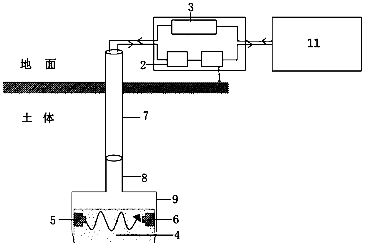
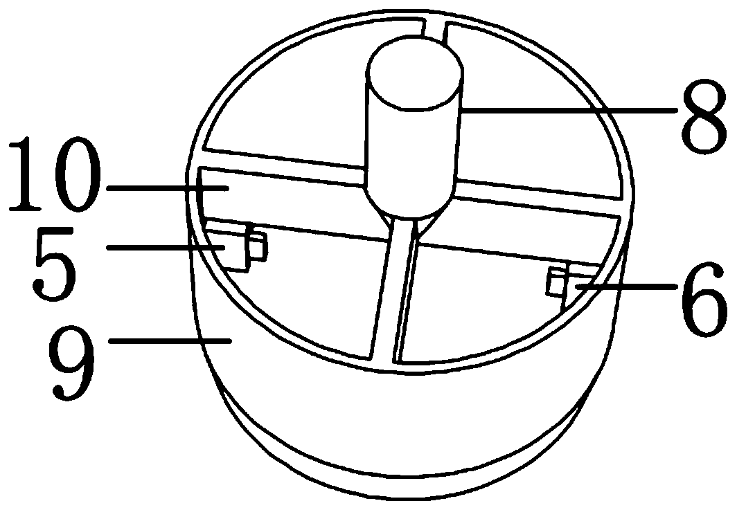
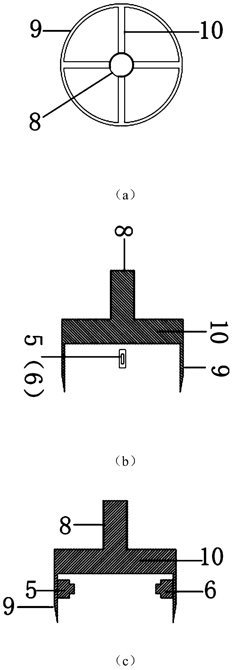
[0035] A flexural element system for in-situ continuous testing of soft soil wave velocities, such as figure 1 As shown, it includes a drill pipe 7 and a probe, the probe is connected to one end of the drill pipe 7, the system also includes a signal generator 3, a signal acquisition device and a host computer 11, the probe includes a transmitter sensor 5 and a receiver sensor 6, and the bottom of the probe is provided There is a ring steel knife 9, the transmitter sensor 5 and the receiver sensor 6 are all bending element sensors, and are respectively connected to the signal generator...


PUM


Abstract

The invention relates to a bending element system used for continuously testing a wave velocity of soft soil in situ, which comprises a drill rod and a probe, wherein the probe is connected to one endof the drill rod; the bending element system also comprises a signal generator, a signal acquisition device and an upper computer; the probe comprises a transmitting end sensor and a receiving end sensor, the bottom of the probe is provided with an annular steel knife, both the transmitting end sensor and the receiving end sensor are bending element sensors, and are respectively connected to thesignal generator and the signal acquisition device, both the signal generator and the signal acquisition device are connected to the upper computer; a waveform signal is generated by the signal generator and is transmitted by the transmitting end sensor, and the receiving end sensor analyzes the acquired waveforms through the signal acquisition device, and then a wave velocity is calculated by theupper computer. In comparison with the prior art, the bending element system of the invention adopts the probe with a reasonable structure, which can be safely and reliably penetrated into the deep part of the soil body, thereby realizing test for the deep soil body.

Description

technical field [0001] The invention relates to the field of soil in-situ testing, in particular to a bending element system for in-situ continuous testing of soft soil wave velocity. Background technique [0002] The shear wave velocity of the soil (v p ) and compression wave velocity (v s ) test has important significance as follows: (1) the elastic modulus E of the soil sample can be calculated 0 and shear modulus G 0 , that is, the modulus of the soil sample under the condition of small strain, which can be used as a parameter of dynamic analysis and also as a parameter of small strain elastoplastic constitutive model. (2) As a non-destructive testing method, the change of the internal structure of the soil can be indirectly characterized by the change of the elastic parameters, which is a necessary supplement to image methods such as scanning electron microscopy. Currently, there are mainly two methods for testing wave velocity: (1) indoor test method (mainly resona...

Claims


Application Information

Patent Timeline
IPC IPC(8): G01H5/00
CPCG01H5/00
Inventor 高彦斌王浩郑晓军姚天骄杨正园
Owner TONGJI UNIV
Learn More