Circuit for measuring temperature of to-be-detected article

A circuit and item technology, applied in the field of temperature measurement, can solve problems such as low accuracy rate and large data deviation, and achieve the effect of small error and high accuracy of measurement data

Inactive Publication Date: 2020-01-17
XUZHOU LIFANG MECHANICAL & ELECTRICAL EQUIP MFG CO LTD
View PDF7 Cites 0 Cited by
  • Summary
  • Abstract
  • Description
  • Claims
  • Application Information

AI Technical Summary

Problems solved by technology

[0002] The current device for testing items is generally a temperature tester, bu

Method used


Image

  • Circuit for measuring temperature of to-be-detected article
  • Circuit for measuring temperature of to-be-detected article

Examples


Embodiment Construction

[0011] The present invention will be further described below in conjunction with accompanying drawing.

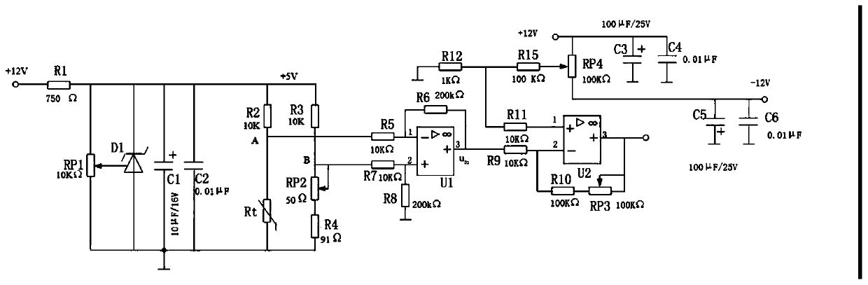
[0012] Such as figure 1 As shown, a circuit for measuring the temperature of the object to be measured is provided in a housing 1, and the housing 1 is a transparent housing, because figure 2 As shown, the circuit includes resistors R1~R13, electrolytic capacitor C1, capacitor C2, electrolytic capacitor C3~C5, capacitor C6, potentiometer RP1~RP4, Zener diode D1, chip U1, chip U2, thermistor Rt, 12V voltage Connect the first fixed end of the potentiometer RP1, the negative pole of the Zener diode D1, the positive pole of the electrolytic capacitor C1, one end of the capacitor C2, one end of the resistor R2, one end of the resistor R2, and the other end of the resistor R2 respectively after passing through the resistor R1. One end of the thermistor Rt, one end of the resistor R5, and the other end of the resistor R3 are respectively connected to the first fixed end of the p...


PUM


Abstract

The invention discloses a circuit for measuring the temperature of a to-be-detected article. The circuit comprises resistors R1 to R13, an electrolytic capacitor C1, a capacitor C2, electrolytic capacitors C3 to C5, a capacitor C6, potentiometers RP1 to RP4, a voltage-stabilized diode D1, a chip U1, a chip U2 and a thermistor Rt. The circuit can measure the temperature of the to-be-detected article at any moment, and measured data is high in precision and small in error.

Description

technical field [0001] The invention relates to a temperature measuring circuit, in particular to a circuit for measuring the temperature of an object to be measured, and belongs to the technical field of temperature measurement. Background technique [0002] At present, the device for testing items is generally a temperature tester, but the data tested by the temperature tester has large deviations and low accuracy. Contents of the invention [0003] Aiming at the above-mentioned problems in the prior art, the present invention provides a circuit for measuring the temperature of the item to be tested, which can accurately measure the temperature parameter of the item to be tested, which is convenient and quick. [0004] In order to achieve the above object, the technical solution adopted by the present invention is: a circuit for measuring the temperature of the object to be measured, including resistors R1 ~ R13, electrolytic capacitor C1, capacitor C2, electrolytic capa...

Claims


Application Information

Patent Timeline
IPC IPC(8): G01K7/22
CPCG01K7/22
Inventor 张彬
Owner XUZHOU LIFANG MECHANICAL & ELECTRICAL EQUIP MFG CO LTD
Why Eureka
Try Eureka