Optical Remote Sensor Using Structural Deformation to Compensate Optical System Misalignment

An optical remote sensor and optical system technology, applied in the field of space remote sensing, can solve the problems of optical components deviating from the optimal position, surface shape accuracy error, difficulty in ensuring large-diameter optical components, etc., so as to achieve the effect of unaffected imaging quality.

Active Publication Date: 2020-12-01
CHANGCHUN INST OF OPTICS FINE MECHANICS & PHYSICS CHINESE ACAD OF SCI
View PDF10 Cites 0 Cited by
  • Summary
  • Abstract
  • Description
  • Claims
  • Application Information

AI Technical Summary

Problems solved by technology

When the remote sensor is launched into orbit and works in the space microgravity environment, the gravitational deformation introduced by the remote sensor when it is installed on the ground will rebound and release, resulting in a certain surface shape accuracy error and pose of each mirror in the remote sensor. Error, the optical element deviates from the best position in the optical system, which makes the optical system out of adjustment, thus affecting the on-orbit imaging quality of the remote sensor
[0004] For the impact of gravity, people have proposed various solutions, such as gravity unloading technology, improved support methods, and lightweight technology. Large-aperture optical components are not misaligned in orbit

Method used


Image

  • Optical Remote Sensor Using Structural Deformation to Compensate Optical System Misalignment
  • Optical Remote Sensor Using Structural Deformation to Compensate Optical System Misalignment
  • Optical Remote Sensor Using Structural Deformation to Compensate Optical System Misalignment

Examples


Embodiment Construction

[0012] The technical solutions in the embodiments of the present invention will be clearly and completely described below in conjunction with the accompanying drawings in the embodiments of the present invention. Obviously, the described embodiments are only part of the embodiments of the present invention, not all of them. Based on the implementation manners in the present invention, all other implementation manners obtained by persons of ordinary skill in the art without making creative efforts belong to the scope of protection of the present invention.

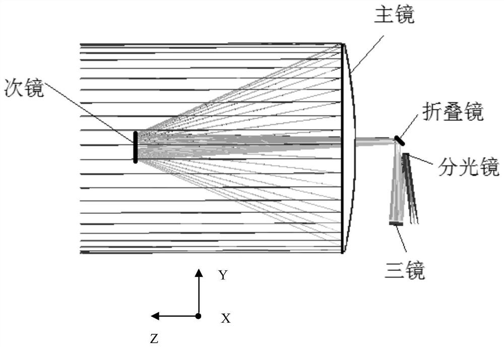
[0013] Please refer to figure 1 , the schematic diagram of the optical path of the optical remote sensor that uses structural deformation to compensate for the misalignment of the optical system provided by the preferred embodiment of the present invention. The optical remote sensor adopts a coaxial reflective optical system. For example, such as figure 1 As shown, the optical remote sensor that uses structural deformation...


PUM


Abstract

An optical remote sensor that uses structural deformation to compensate for the misalignment of an optical system, including a primary mirror, a secondary mirror, a folding mirror, a beam splitter, three mirrors, a main load-bearing frame and an elastic support rod; the main load-bearing frame includes a front mounting surface and the rear mounting surface opposite to the front mounting surface; the primary mirror is elastically installed on the front mounting surface, the secondary mirror is elastically connected to one end of the support rod and is opposite to the primary mirror, and the end of the support rod away from the secondary mirror is connected to the front mounting surface connection; the folding mirror and the beam splitter are installed on the rear installation surface; the three mirrors are installed on the rear installation surface and are opposite to the beam splitter at intervals. The invention makes the primary mirror and the secondary mirror deviate from the theoretical position through the deformation amount under the action of gravity, so that the optimal pose of the primary mirror and the secondary mirror installed under the action of gravity on the ground will be deformed by gravity after the space remote sensor is launched into orbit When the rebound is released, the positional relationship between the primary mirror and the secondary mirror can still maintain the positional relationship during assembly and adjustment, and the imaging quality of the space remote sensor will not be affected.

Description

technical field [0001] The invention relates to the technical field of space remote sensing, in particular to an optical remote sensor which uses structural deformation to compensate the misalignment of an optical system. Background technique [0002] Space optical remote sensors have important applications in astronomical observation, space exploration, weather forecasting, earth observation, military applications and other fields. With the continuous development of space remote sensing technology, the resolution requirements for space optical remote sensors are getting higher and higher, and the requirements for focal length and aperture of optical systems are also increasing. [0003] As the focal length and aperture of space optical remote sensors continue to increase, their size and weight also increase sharply. When the remote sensor is assembled and tested on the ground, the gravity will affect the surface shape accuracy and pose accuracy of the large-scale reflector,...

Claims


Application Information

Patent Timeline
Patent Type & Authority Patents(China)
IPC IPC(8): G02B7/182G02B7/00
CPCG02B7/182G02B7/00
Inventor 邵明东郭疆李宪斌李元鹏周龙加
Owner CHANGCHUN INST OF OPTICS FINE MECHANICS & PHYSICS CHINESE ACAD OF SCI
Why Eureka
Try Eureka