ROS based control system and method for unmanned aerial vehicles

A multi-UAV and control system technology, applied in the direction of control/adjustment system, attitude control, non-electric variable control, etc., can solve problems such as inability to continue rescue, affect rescue efficiency, and limited effect, so as to improve environmental adaptability, Improve the efficiency of task execution and the effect of various control methods

Pending Publication Date: 2020-01-17
HECHI UNIV
View PDF0 Cites 11 Cited by
  • Summary
  • Abstract
  • Description
  • Claims
  • Application Information

AI Technical Summary

Problems solved by technology

The role of a single UAV is limited. For example, when detecting a building fire, it can only detect a blind spot in a certain direction at the same time, so that it fails to detect emergencies in time and leads to heavy losses. It is also possible that a single UAV In the fire rescue process, damage may occur due to sudden changes in the fire, resulting in the inability to continue the rescue, which seriously affects the rescue efficiency. Multi-drones can monitor this kind of problem in all directions in real time and can implement emergency treatment for emergencies that occur somewhere. As soon as an emergency occurs, it can be dealt with in its infancy. Even if some drones are damaged during the rescue process, the remaining drones can complete the rescue, solving the problem of equipment failure. Unable to continue rescue problem

Method used


Image

  • ROS based control system and method for unmanned aerial vehicles
  • ROS based control system and method for unmanned aerial vehicles
  • ROS based control system and method for unmanned aerial vehicles

Examples


Embodiment Construction

[0044] The present invention will be further described below in conjunction with the drawings and embodiments. It should be noted that the specific embodiments of the present invention are only for describing the technical solution more clearly, and cannot be used as a limitation of the protection scope of the present invention.

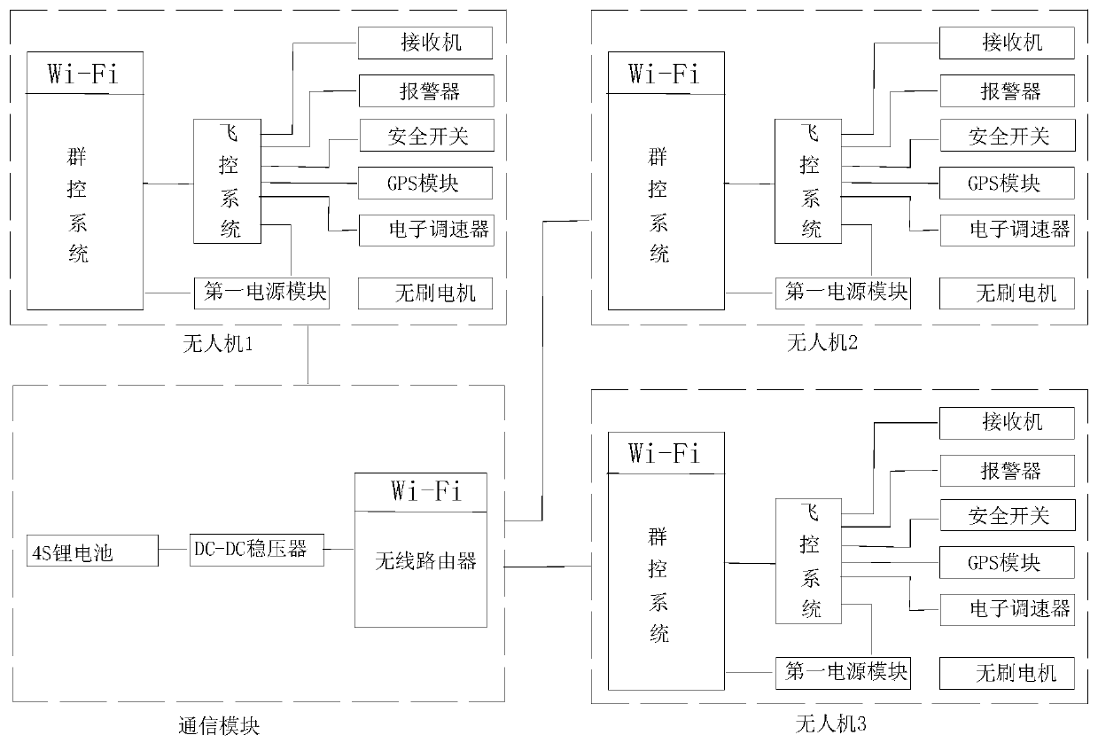
[0045] See Figure 1-Figure 8 , A multi-UAV control system based on ROS, including a communication module, a first power module and multiple drones, each drone includes a group control system set on a group control board and a flight control board The communication module is connected to a plurality of drones; the group control system is connected to the flight control system; the first power module is connected to the group control system and the flight control system, respectively ;

[0046] The group control system uses Raspberry 3Pi Mode B as the top-level controller, which is used to collect the position information of each drone in the system, obta...


PUM


Abstract

The invention relates to an ROS based control system for unmanned aerial vehicles, and belongs to the technical field of aircraft cooperative control. The system comprises a communication module, a first power supply module and the unmanned aerial vehicles, and each unmanned aerial vehicle comprises a group control system and a flight control system; the group control system is used for acquiringposition information of each unmanned aerial vehicle in the system, acquiring GPS coordinates of the corresponding unmanned aerial vehicle, issuing the GPS coordinates to other unmanned aerial vehicles in the system, receiving control data sent by a ground control station, and sending the control data to the flight control system for operation after data processing; the flight control system is used for receiving a control instruction of the group control system, collecting position information and speed information of the unmanned aerial vehicle and controlling the flight mode, height, speedand heading of the unmanned aerial vehicle; the group control system makes information interaction with each unmanned aerial vehicle through the communication module, and the unmanned aerial vehiclescommunicate with one other through the communication module; and the first power supply module is used for supplying power to the group control system and the flight control system. The task executionefficiency can be improved, and the stability of cooperative application of multiple unmanned aerial vehicles can be improved.

Description

Technical field [0001] The invention relates to the technical field of aircraft cooperative control, in particular to a ROS-based multi-UAV control system and a control method thereof. Background technique [0002] UAVs not only have unparalleled superiority in military strikes and defenses, but are also widely used in civilian fields such as emergency medical delivery, fire disaster relief, geological exploration, and electrical maintenance due to their flexibility and high mission efficiency. . The role of a single drone is limited. For example, when detecting a building fire, it can only detect a blind spot in a certain direction at the same time, so that it cannot detect an emergency in time and cause heavy losses. There may be a single drone. During the fire disaster relief process, damage may occur due to sudden changes in the fire, resulting in the inability to continue the rescue, which seriously affects the rescue efficiency. For this type of problem, multiple drones ca...

Claims


Application Information

Patent Timeline
Patent Type & Authority Applications(China)
IPC IPC(8): G05D1/08G05D1/10
CPCG05D1/0011G05D1/0816G05D1/104
Inventor 彭建盛覃剑覃勇何奇文韦庆进徐咏
Owner HECHI UNIV
Why Eureka
Try Eureka