Improved welt bifurcated pipe calculation model

A technology for calculating models and welt bifurcated pipes is applied in the field of calculation models for welt bifurcated pipes, which can solve the problems of inaccurate calculation results, low calculation accuracy, and low calculation accuracy of shell elements, and achieve the effect of efficient structural design.

Pending Publication Date: 2020-01-17
POWERCHINA CHENGDU ENG
View PDF3 Cites 2 Cited by
  • Summary
  • Abstract
  • Description
  • Claims
  • Application Information

AI Technical Summary

Problems solved by technology

The first two methods have certain limitations, and the calculation accuracy is not high. They mainly rely on engineering experience for structural design. The design scheme is generally too conservative, and it is difficult to design large-scale welted bifurcation pipes.
[0003] The finite element method mainly adopts the shell element calculation model, and the main problems of this model include: (1) Generally, the shell element is used to establish the numerical model, and the calculation accuracy of the shell element is not high
(2) Considering the main and branch pipe main plates and reinforcing plates in the reinforcement area as one, and using single-layer shell elements for simulation, it is impossible to analyze the structural stress and safety evaluation of the main plate and reinforcing plates separately according to the requirements of the code, and thus it is impossible to carry out Targeted optimization design of main board and reinforcement board
(3) Since the reinforcement area is simulated by single-layer shell elements, and the default shell element mid-plane alignment is adopted, the numerical model is inconsistent with the actual design scheme and the calculation results are inaccurate

Method used


Image

  • Improved welt bifurcated pipe calculation model
  • Improved welt bifurcated pipe calculation model
  • Improved welt bifurcated pipe calculation model

Examples


Embodiment

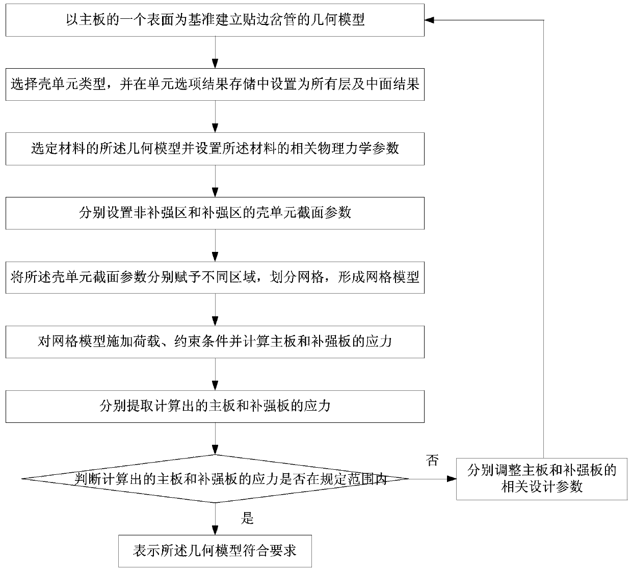
[0053] An improved calculation model for welted bifurcated pipes in the embodiment of the present invention is suitable for structural analysis of multilayer reinforced plate welted bifurcated pipes, and mainly includes the following steps:

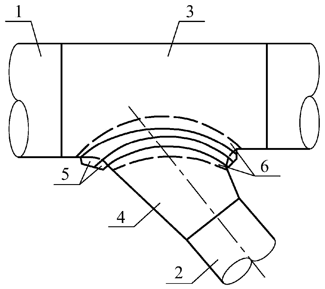
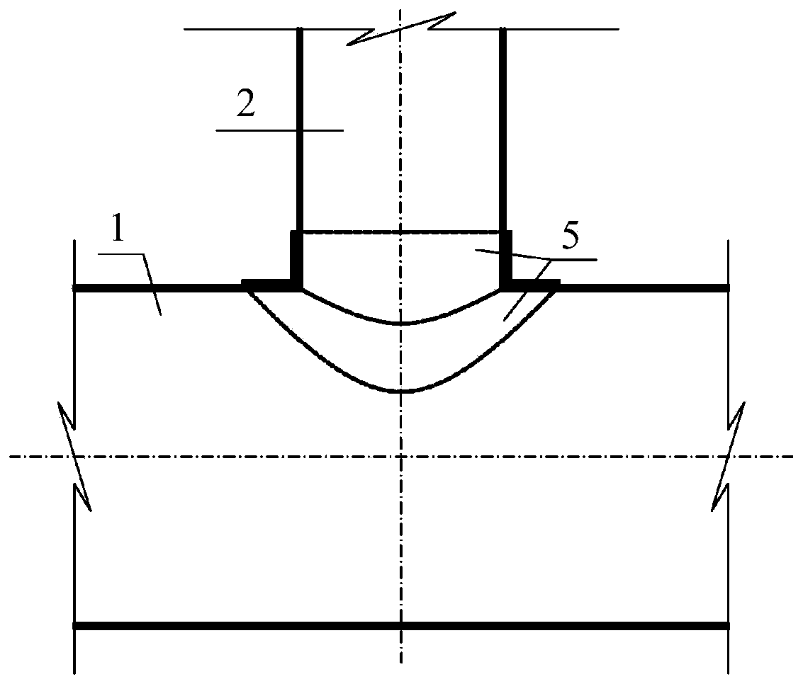
[0054] Build a geometric model: according to Figure 2 ~ Figure 6 The design drawing of the welted bifurcation, figure 2 is a schematic diagram of a typical welt bifurcation pipe, image 3 is the longitudinal section design drawing of the welt bifurcation pipe, Figure 4 It is the top view design drawing of the welted bifurcation pipe, Figure 5 It is a local large-scale sample diagram of the reinforcement area of ​​the welted bifurcation pipe. For the local diagram of the geometric model of the welted bifurcation pipe in the ANSYS software, please refer to Figure 6 , including: supervisor 1, main board 11, branch pipe 2, main board 21 of branch pipe, main cone pipe 3, branch cone pipe 4, outer reinforcing plate 5, first layer outer ...


PUM


Abstract

The invention provides an improved welt bifurcated pipe calculation model, and belongs to the field of welt bifurcated pipe calculation models. The method according to the invention is characterized by comprising the steps of establishing a geometric model of the welt bifurcated pipe with one surface of a main plate as the benchmark; selecting a shell unit type, and setting all layer and middle surface results in unit option result storage; selecting the geometric model of the material and setting related physical and mechanical parameters of the material; setting shell unit section parametersof the non-reinforcing area and the reinforcing area respectively; endowing different areas with the shell unit section parameters respectively, and dividing grids to form a grid model; applying a load and a constraint condition to the grid model and calculating stresses of the main board and the stiffening plate; respectively extracting the calculated stresses of the main board and the stiffening plate; and judging whether the calculated stresses of the main board and the stiffening plate are within a specified range, if yes, indicating that the geometric model meets the requirements, and otherwise, respectively adjusting related design parameters of the main board and the stiffening plate until the geometric model meets the requirements.

Description

technical field [0001] The invention relates to the field of calculation models of side-facing bifurcation pipes, in particular to an improved calculation model of side-facing bifurcation pipes. Background technique [0002] Welted bifurcated pipes are provided with reinforcing plates that closely fit the pipe shell on the inside and / or outside within a certain range on both sides of the main and branch pipe intersecting lines. There are mainly area compensation method, ring method and finite element method for the structural analysis of side bifurcation pipes. The first two methods have certain limitations, and the calculation accuracy is not high. The structural design is mainly based on engineering experience. The design scheme is generally too conservative, and it is difficult to design large-scale welted bifurcation pipes. [0003] The finite element method mainly adopts the shell element calculation model, and the main problems of this model include: (1) The numerical...

Claims


Application Information

Patent Timeline
IPC IPC(8): G06F30/23G06F119/14
CPCY02T90/00
Inventor 孙博杜超
Owner POWERCHINA CHENGDU ENG
Why Eureka
Try Eureka