Laser point cloud-based lane line identification method and system

A technology of lane line recognition and laser point cloud, which is applied in the field of lane recognition, can solve the problems that the speed of laser point cloud is not particularly high and it is difficult to meet the dynamic needs, so as to reduce the probability of lane misidentification, reduce storage space and cost, and information obvious effect

Inactive Publication Date: 2020-01-17
芜湖酷哇机器人产业技术研究院有限公司
View PDF1 Cites 22 Cited by
  • Summary
  • Abstract
  • Description
  • Claims
  • Application Information

AI Technical Summary

Problems solved by technology

At the same time, since the speed of the laser point cloud is not particularly high (generally about 10-20Hz), when the car body has a relatively fast speed, it is difficult to meet the dynamic needs of the laser point cloud in one circle of data if the same time is used

Method used


Image

  • Laser point cloud-based lane line identification method and system
  • Laser point cloud-based lane line identification method and system
  • Laser point cloud-based lane line identification method and system

Examples


Embodiment Construction

[0052] The present invention will be described in detail below in conjunction with specific embodiments. The following examples will help those skilled in the art to further understand the present invention, but do not limit the present invention in any form. It should be noted that those skilled in the art can make several changes and improvements without departing from the concept of the present invention. These all belong to the protection scope of the present invention.

[0053] In the prior art, the laser needs to obtain as much information about the lane line as possible for the low speed of the vehicle, and then pass a series of judgments (including methods such as clustering) according to the reflection intensity information to determine whether it is a lane line. At the same time, the frequency of lidar is generally low (10-20HZ). When the vehicle speed is fast, the point cloud itself will produce motion distortion, which often occurs on high-speed vehicles. If no mo...


PUM


Abstract

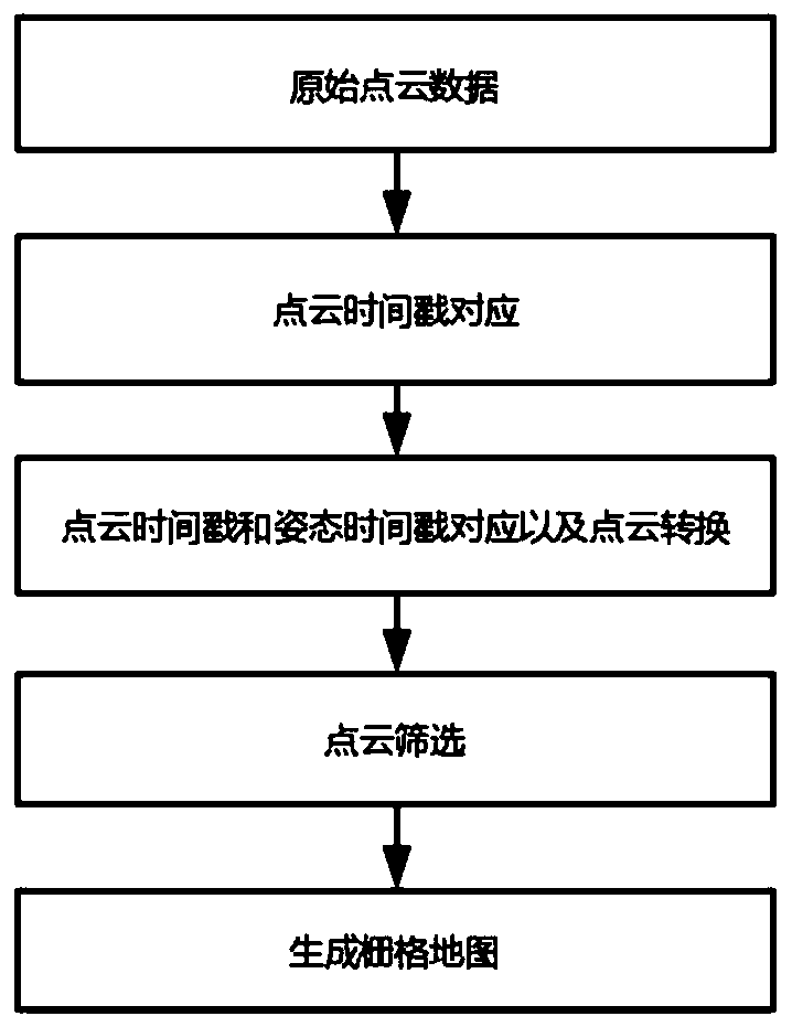
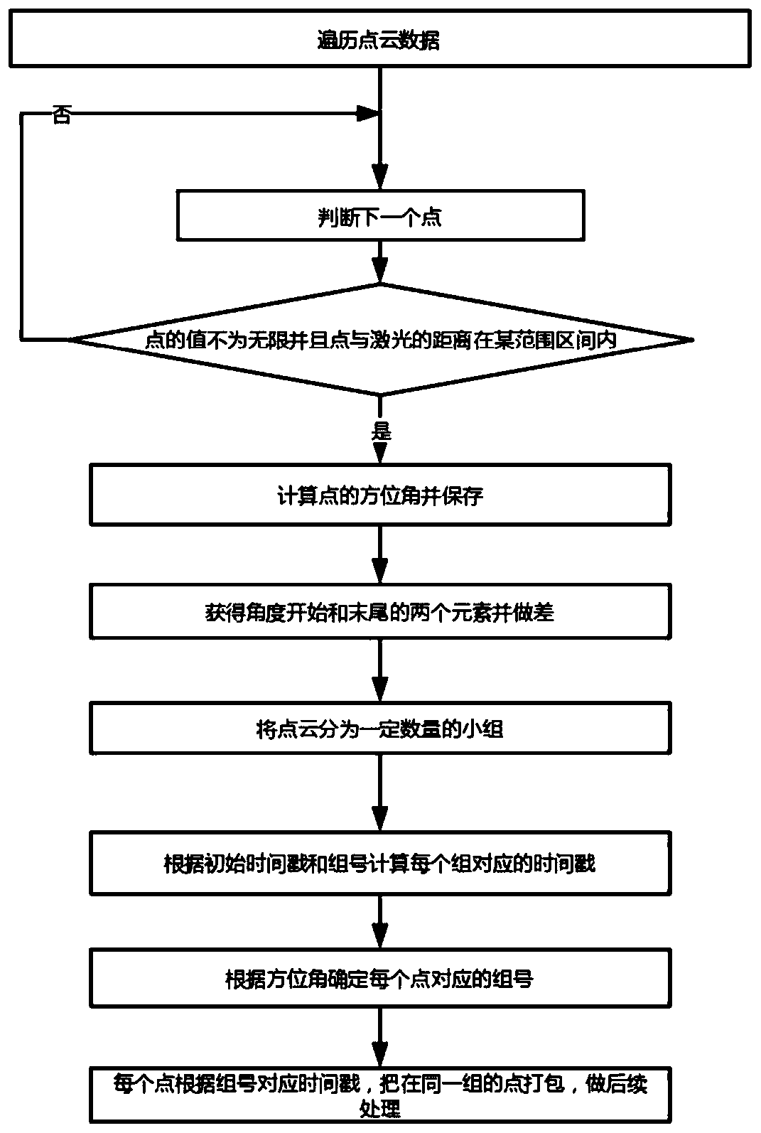
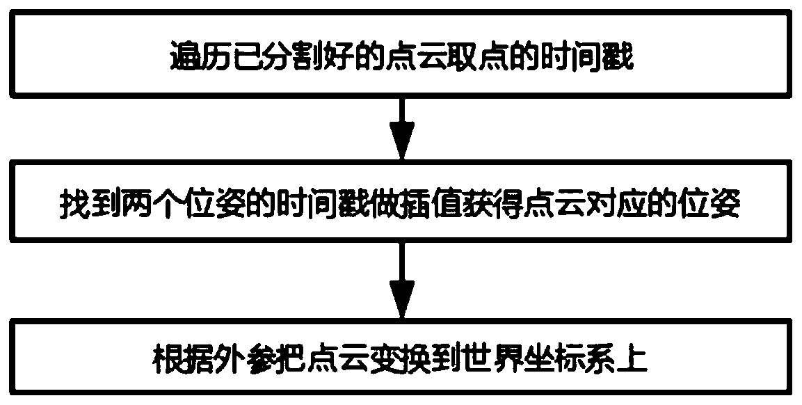
The invention provides a laser point cloud-based lane line identification method and system. The method comprises the steps of generating a point cloud timestamp capable of uniquely identifying each laser point cloud point according to an azimuth angle; converting to a world coordinate system according to the pose timestamp and the relative position relationship between the laser and the world coordinate system; traversing the laser point clouds under the world coordinate system, and screening the laser point clouds according to the driving track and the heading to obtain region-of-interest point clouds; and generating a grid map according to the point coordinates of the point cloud of the region of interest and the reflection intensity of the laser point cloud. According to the method andsystem, the point clouds are grouped, each group of point clouds has a corresponding pose instead of giving a pose to each general frame of point clouds, and the precision during high-speed driving is improved. A large part of point cloud data is filtered and screened out according to actual requirements, and the lane line information is obvious through rasterization, so that the storage space and cost are reduced, and meanwhile, the probability of lane error identification in a non-interested area is greatly reduced.

Description

technical field [0001] The invention relates to the technical field of lane recognition, in particular to a method for lane line recognition based on a laser point cloud. Background technique [0002] In the existing technology, when the laser point cloud extracts the lane line, the vehicle speed is generally relatively low, so that the lidar can emit as many point cloud points as possible distributed on the ground and the lane line, and then identify the lane from the difference in reflection intensity of these points Wire. At the same time, since the rotation speed of the laser point cloud is not particularly high (generally around 10-20Hz), when the car body has a relatively fast speed, it is difficult to meet the dynamic needs if the time of the laser point cloud in one circle of data is used at the same time. [0003] The existing technology related to this application is the patent document CN105488498A, which discloses a method and system for automatically extracting...

Claims


Application Information

Patent Timeline
Patent Type & Authority Applications(China)
IPC IPC(8): G06K9/32G06K9/00G06T7/70G01S7/48
CPCG06T7/70G01S7/4802G06V20/588G06V10/25
Inventor 何弢廖文龙尤鑫
Owner 芜湖酷哇机器人产业技术研究院有限公司
Why Eureka
Try Eureka