Supercharge Your Innovation With Domain-Expert AI Agents!

Discharging device of automatic vending machine

A technology for vending machines and shipping devices, which is applied to instruments, coin-operated equipment for distributing discrete items, and coin-operated equipment for distributing discrete items, etc. and other problems, to achieve the effect of improving work reliability, convenient and reliable shipment, and saving delivery time.

Pending Publication Date: 2020-01-17
常州剑湖金城车辆设备有限公司
View PDF2 Cites 2 Cited by
  • Summary
  • Abstract
  • Description
  • Claims
  • Application Information

AI Technical Summary

Problems solved by technology

For the delivery mechanism using spring cargo lanes, the springs set on the cargo lanes are usually connected to the driving part of the motor in a clamping manner. When shipping, the springs are driven by the motor to push the corresponding goods out of the cargo lanes through the corresponding channels. Sliding or rolling down to the delivery port, the spring connected to the motor in the way of clipping is likely to cause the drive to loosen during long-term use and the goods cannot be successfully pushed, resulting in the vending machine with spring-type cargo lanes prone to failure to deliver after payment In addition, the spring-loaded cargo lane must be pulled out as a whole to load the goods, and the requirements for how to place the loaded goods are high, making loading time-consuming and laborious
The crawler cargo lane is to set more than one crawler belt in each cargo lane, and at least one push plate is set on each crawler belt and equipped with a driving motor (see the application publication number CN108038972A, and the name is vending machine delivery mechanism The Chinese patent document of this kind of vending machine that adopts the crawler cargo lane is delivered by the crawler belt. During the use process, the crawler belt is likely to be stuck due to the tilt of the goods and other reasons, and the goods cannot be successfully pushed, and the goods must be placed on the cargo lane when loading. Each push plate set can be pushed backwards to load the goods, which has high requirements on the placement and placement of the goods, which also makes the loading time-consuming and laborious
In addition to the above-mentioned problems that are prone to failure to ship smoothly and time-consuming and laborious loading, there is also a common problem in the above-mentioned automatic vending machines that use spring cargo lanes or crawler cargo lane delivery devices: each cargo lane needs to be installed accordingly. A drive mechanism mainly composed of motors, because the vending machine has many cargo lanes (usually 20 or 30 cargo lanes), so the corresponding number of drive mechanisms (motors) that need to be installed makes the cost of the vending machine relatively high. High, and make the electrical structure complex, high failure rate during use
[0003] In order to solve the problem that the above-mentioned consumers cannot ship smoothly because the goods are stuck after the payment is completed, the application publication number is CN108492463A, and the Chinese patent document named a kind of automatic vending machine delivery device and automatic vending machine adopts a The delivery mechanism mainly consists of a spiral tube connected to the drive motor. Although it can solve the problem of cargo jamming to a certain extent, it still has the problems of complex electrical structure and many required motors.

Method used


Image

  • Discharging device of automatic vending machine
  • Discharging device of automatic vending machine
  • Discharging device of automatic vending machine

Examples


Embodiment 1)

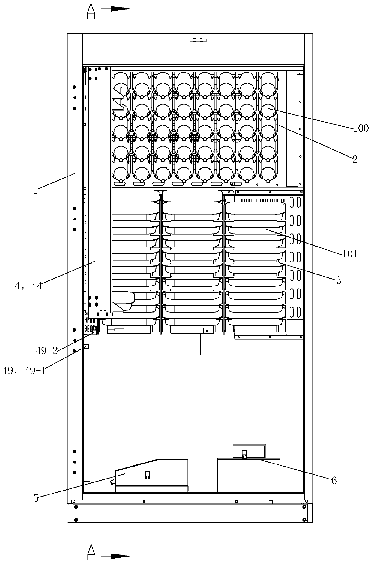
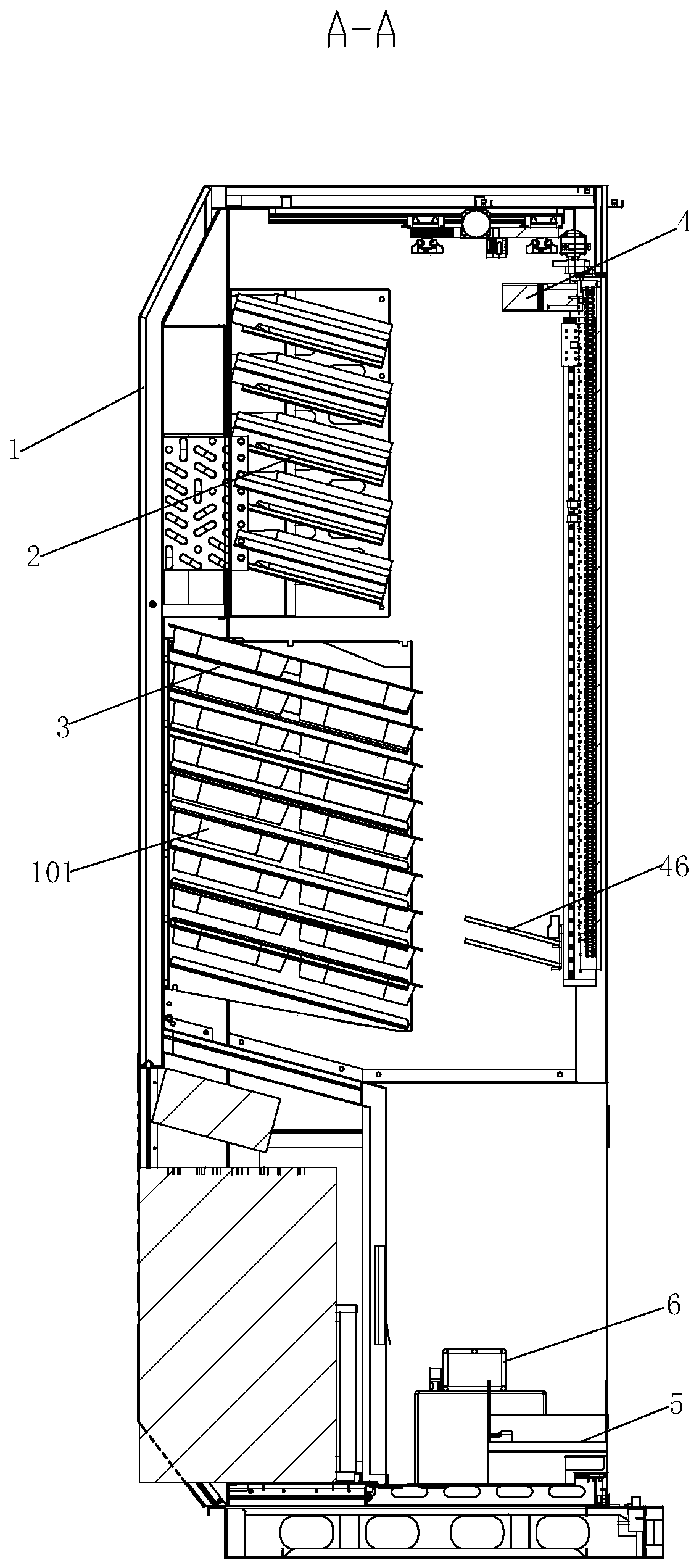
[0048] See figure 1 and figure 2 , the automatic vending machine shipping device of the present embodiment, it is mainly made up of body 1, beverage shelf 2, box-shaped goods shelf 3, automatic delivery mechanism 4, beverage delivery box 5 and box-shaped goods delivery shelf 6.

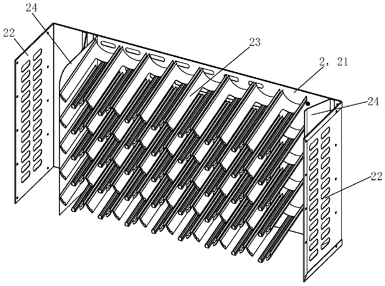
[0049] see image 3 , Beverage shelf 2 is mainly made up of rear panel 21, side panel 22 and beverage goods channel 23. Side plate 22 is provided with 2 pieces, and 2 pieces of side plates 22 are integrally or fixedly connected with the left and right sides of rear plate 21 and protrude forward, as preferred mode, rear plate 21 and 2 pieces of side plates 22 are all provided with some air-permeable hole. Beverage cargo lanes 23 are arranged in more than 2 rows parallel to the left and right and more than 2 rows are arranged in parallel up and down. Between the side plates 22, each beverage cargo channel 23 is fixedly arranged on the rear panel 21 in a way that the front end is lower than the rear...


PUM


Abstract

The invention provides a discharging device of an automatic vending machine. The discharging device comprises a body, a beverage shelf, a box-like goods shelf and an automatic discharging mechanism, wherein the beverage shelf, the box-like goods shelf and the automatic discharging mechanism are fixedly arranged in the body; beverage channels which are arranged vertically and horizontally and incline forwards are formed in the beverage shelf, and box-like goods channels which are arranged vertically and horizontally and incline forwards are formed in the box-like goods shelf; and the automaticdischarging mechanism comprises a manipulator used for taking and conveying goods, a forward and backward driving mechanism used for driving the manipulator to move forwards and backwards, a leftwardand rightward driving mechanism used for driving the manipulator to move leftwards and rightwards, an upward and downward driving mechanism used for driving the manipulator to move upwards and downwards, a mechanical arm used for installing the upward and downward driving mechanism and the manipulator and a mechanical arm rotation driving mechanism used for driving the mechanical arm and the manipulator to do 90-degree rotational motion. According to the discharging device, through the structural design of the self-slide-down channels and the automatic discharging mechanism, the problems thatin the prior art, similar automatic vending machines are complicated in structure and high in cost, feeding and discharging are not convenient, and goods are prone to getting stuck can be effectivelysolved.

Description

technical field [0001] The invention relates to an automatic vending machine, in particular to a delivery device of the automatic vending machine. Background technique [0002] The structure of the delivery device of the vending machine varies according to the goods sold. Currently common vending machines for selling bottled beverages and box-shaped items (such as boxed lunches), the delivery device usually consists of a cargo lane and a driving mechanism. The cargo lane usually adopts a spring cargo lane or a crawler cargo lane. Each cargo lane Equipped with a set of driving mechanism mainly composed of motor. For the delivery mechanism using spring cargo lanes, the springs set on the cargo lanes are usually connected to the driving part of the motor in a clamping manner. When shipping, the springs are driven by the motor to push the corresponding goods out of the cargo lanes through the corresponding channels. Sliding or rolling down to the delivery port, the spring conn...

Claims


Application Information

Patent Timeline
IPC IPC(8): G07F11/28
CPCG07F11/28
Inventor 陈思德周权喜周迅
Owner 常州剑湖金城车辆设备有限公司
Features
  • R&D
  • Intellectual Property
  • Life Sciences
  • Materials
  • Tech Scout
  • Unparalleled Data Quality
  • Higher Quality Content
  • 60% Fewer Hallucinations
Learn More