Supercharge Your Innovation With Domain-Expert AI Agents!

Stand-alone cutting apparatus

A cutting device, cutter technology, applied in the direction of printing device, packaging, transportation and packaging, etc., can solve the problem of unclear cutter rotation, printer cutting equipment blocking, supply roller edge printer or cutting equipment blocking and other problems

Active Publication Date: 2020-01-17
AVERY DENNISON CORP
View PDF10 Cites 0 Cited by
  • Summary
  • Abstract
  • Description
  • Claims
  • Application Information

AI Technical Summary

Problems solved by technology

However, tests on printer stock have shown that steeper profiles (such as about a 60 degree angle) can catch the edge of the stock and jam the carriage of a printer or cutting device
Moderate profiles (such as about a 45 degree angle) move over the edge of the stock, but bounce can result in short pierce cuts, which is not desired
The lower profile (such as about a 25 degree angle) moves over the edge of the stock, but the leading edge is not perfect, most likely caused by the cutter bouncing over the leading edge of the stock
Also, if the stock is not lying flat on the anvil, edge damage can be a problem when this type of cutter moves into the stock
[0008] While flatter blade angles are generally easier to ride on the leading edge, any damage to the edge of the supply roll could still cause a jam in the printer or cutting equipment
Additionally, these types of cutters tend to wear out quickly, which over time can lead to imperfect cuts of the stock and frequent downtime when repairing (eg, sharpening) or replacing cutters
Adhesive can also build up on the cutter blades, exacerbating the problem
Also, if the media being cut is not maintained under tension, it may cause a jam in the printer or other cutting equipment
A blade with a flatter cutting angle and the anvil it rests against to cut is also prone to premature wear and damage
There is also a limit to how fast the cutter can travel without bouncing
Also, it is unclear whether turning this type of cutter 180° to turn and cut back will have an adverse effect on the overall life of the cutter, printer or other equipment

Method used


Image

  • Stand-alone cutting apparatus
  • Stand-alone cutting apparatus
  • Stand-alone cutting apparatus

Examples


Embodiment Construction

[0057] The present invention is now described with reference to the drawings, wherein like reference numerals are used to refer to like elements throughout. In the following description, for purposes of explanation, numerous specific details are set forth in order to provide a thorough understanding. It is evident, however, that innovations can be practiced without these specific details. In other instances, well-known structures and devices are shown in block diagram form in order to facilitate their description.

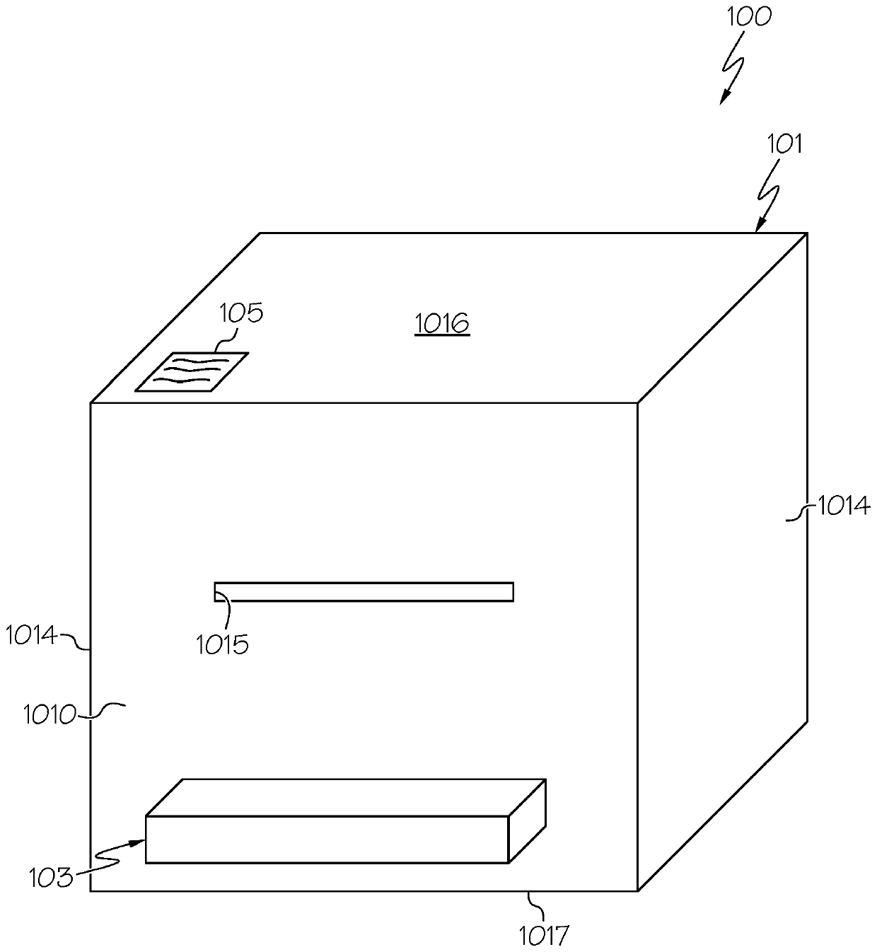
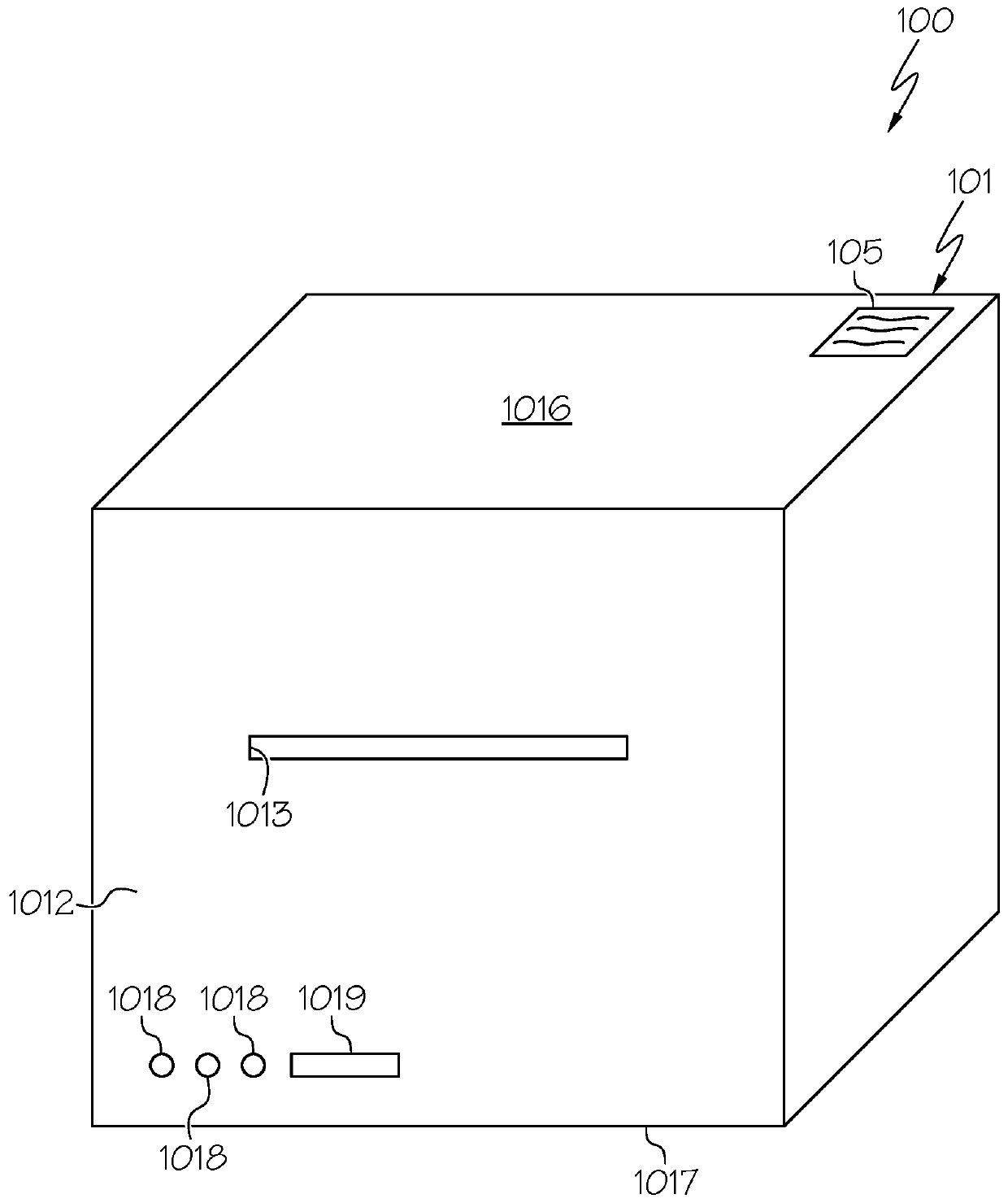
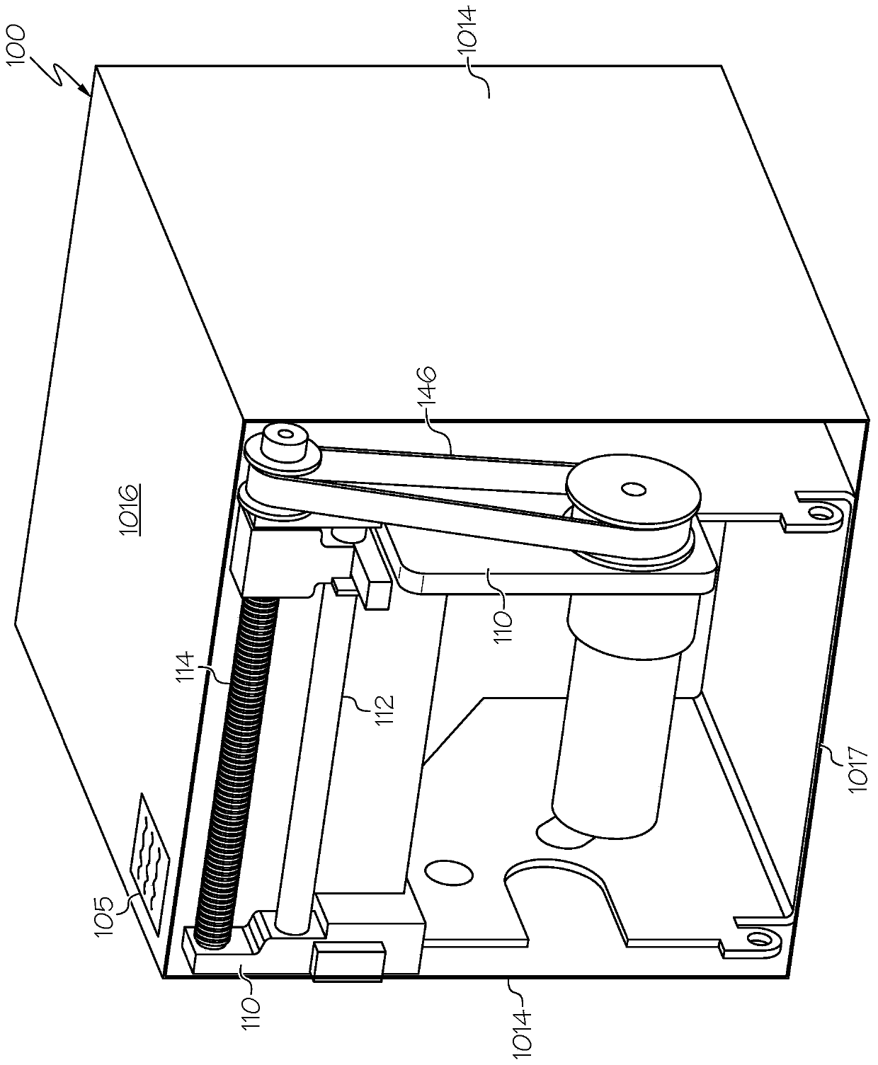
[0058] The present invention discloses a self-contained cutting device that can quickly and cleanly cut or "nip cut" a web of media stock 20 (such as a sheet of paper laminate, vinyl, or RFID stock) in a front-to-rear direction. material) without damaging the cutting blade or the material. Specifically, the cutting device of the present invention can perform "die-cutting"-like cutting on the stock material 20 without the same structural and operational limitation...


PUM


Abstract

The invention discloses a stand-alone apparatus for cutting a web of media or tag stock into individual units for use downstream of a printer. The apparatus may cut vinyl, plastic, or RFID stock material in both back and forth directions. The apparatus comprises a housing, a carriage assembly and a movable cutter assembly. The cutter assembly is easily interchangeable and comprises a cutting element such as a wheel blade, and a pressure adjusting element for adjusting the amount of pressure applied by the cutting element to the stock material. Alternatively, the cutter assembly may be manufactured with a predetermined pressure load, but still permit an operator to adjust the depth of cut. The apparatus may be powered by and or in hardline or wireless communication with a printer, or may further comprise a computer microprocessor, memory and user interface to function wholly independent from a printer.

Description

[0001] Cross References to Related Applications [0002] This application claims U.S. Provisional Application No. 62 / 492,500, filed May 1, 2017, U.S. Provisional Application No. 62 / 552,240, filed August 30, 2017, U.S. Provisional Application No. 62 / 552,248, filed August 30, 2017 and priority to and benefit of U.S. Provisional Application No. 62 / 552,252, filed August 30, 2017, each of which is hereby incorporated by reference in its entirety. Background technique [0003] The present invention generally relates to a portable, self-contained device for cutting media, such as prints on the media, to create "kiss cut" or "die cut" like labels on demand. Traditional methods of producing pressure sensitive label matrices primarily involve die cutting or etching or marking processes by blade or laser. For example, die cutting is typically performed with a flatbed or rotary mechanism and involves the process of using a die to cut a web of low strength material, such as pressure sensi...

Claims


Application Information

Patent Timeline
Patent Type & Authority Applications(China)
IPC IPC(8): B26D1/18
CPCB26D1/185B26D7/2635B26F1/38B26D5/08B26D1/205B26D5/007B26D3/085Y10T156/1184Y10T156/1195Y10T156/1967Y10T156/1961Y10T156/1994B26D7/2621B26D2007/005B65C9/1803B31D1/026B31D1/021B65C2009/1834B32B38/10B32B43/006B41J11/66
Inventor D·J·沃德J·D·米斯蒂乌里克T·L·布朗J·M·沃森J·小罗莫J·R·惠勒M·G·斯坦恩J·F·达克特
Owner AVERY DENNISON CORP
Features
  • R&D
  • Intellectual Property
  • Life Sciences
  • Materials
  • Tech Scout
  • Unparalleled Data Quality
  • Higher Quality Content
  • 60% Fewer Hallucinations
Learn More