Machining device for circular pipe spiral groove

A processing device and a technology of spiral grooves, applied in the field of mechanical processing, can solve the problems of reducing work efficiency, processing degree, and no round pipe cutting and grinding treatment.

Active Publication Date: 2020-01-21
景宁丽恒模具加工厂
View PDF4 Cites 10 Cited by
  • Summary
  • Abstract
  • Description
  • Claims
  • Application Information

AI Technical Summary

Problems solved by technology

At present, the drawing methods in production can be roughly divided into three types: reducing diameter drawing, reducing outer wall drawing and reducing inner wall drawing. The corresponding deformation mostly goes through three stages of diameter reduction, wall reduction and sizing, and the corresponding stress is generated inside the deformation zone, in which the axial direction is tensile stress, the radial and circumferential directions are compressive stress, and the metal is...

Method used


Image

  • Machining device for circular pipe spiral groove
  • Machining device for circular pipe spiral groove
  • Machining device for circular pipe spiral groove

Examples


Embodiment Construction

[0033] The technical solution of the present invention will be further described below in conjunction with the accompanying drawings and through specific implementation methods.

[0034] Wherein, the accompanying drawings are only for illustrative purposes, showing only schematic diagrams, rather than physical drawings, and should not be construed as limitations on this patent; in order to better illustrate the embodiments of the present invention, some parts of the accompanying drawings will be omitted, Enlargement or reduction does not represent the size of the actual product; for those skilled in the art, it is understandable that certain known structures and their descriptions in the drawings may be omitted.

[0035] In the drawings of the embodiments of the present invention, the same or similar symbols correspond to the same or similar components; , "inner", "outer" and other indicated orientations or positional relationships are based on the orientations or positional r...


PUM


Abstract

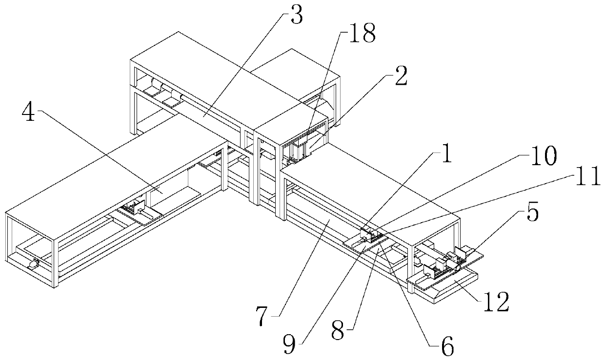
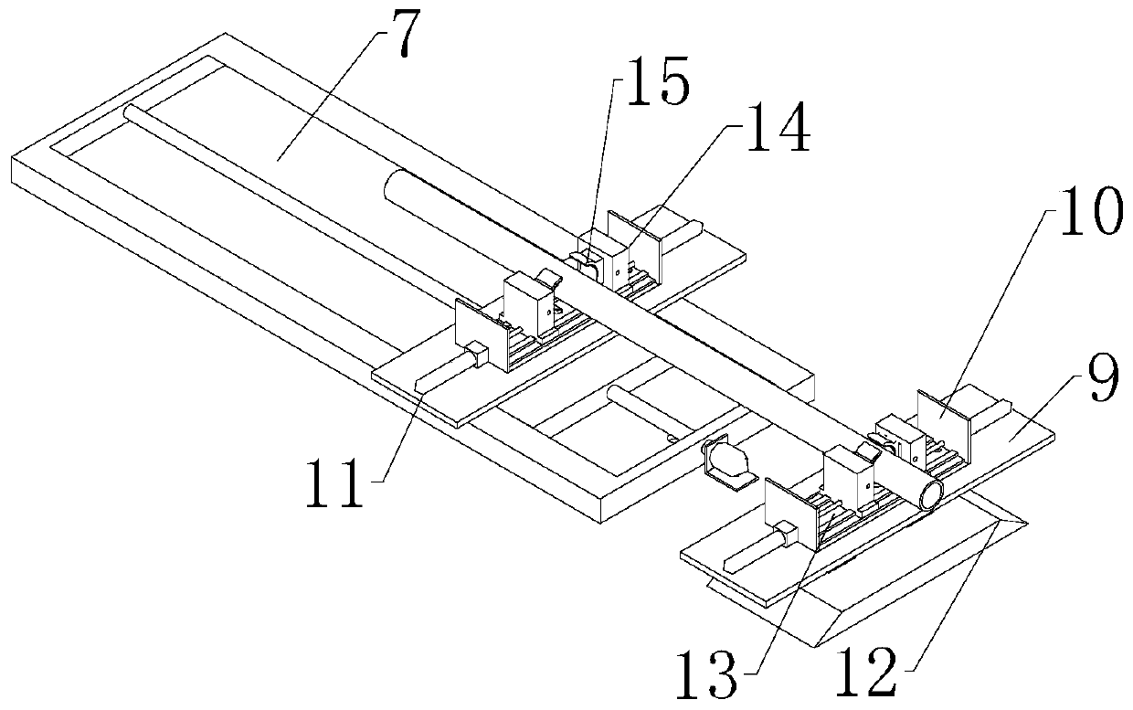
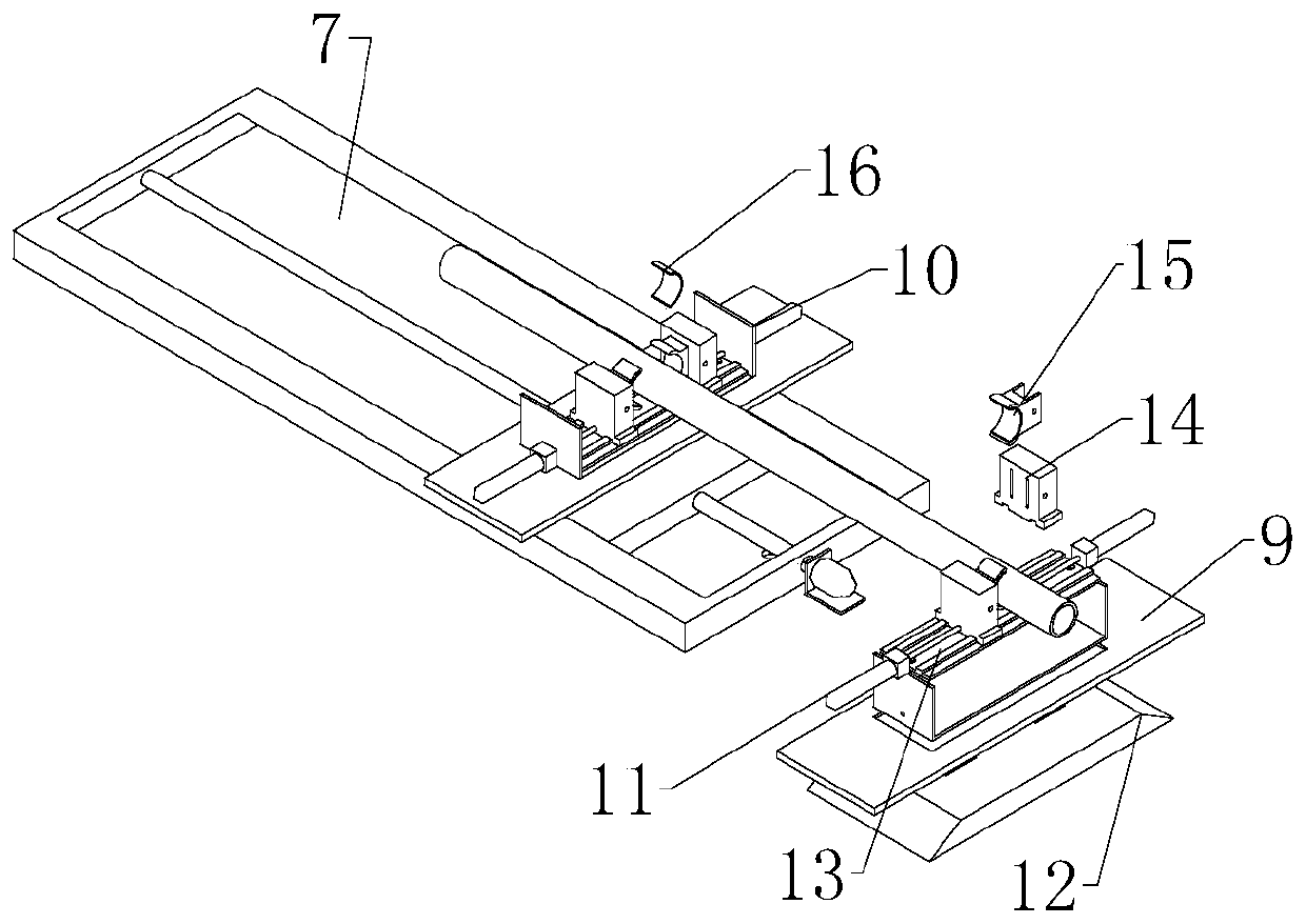
The invention relates to the field of machining, and specifically relates to a machining device for a circular pipe spiral groove. The machining device comprises a feeding assembly, a cutting assembly, a grinding assembly and a machining assembly, wherein the feeding assembly is arranged at one end of the cutting assembly; the grinding assembly is arranged at the end, away from the feeding assembly, of the cutting assembly; the machining assembly is arranged on one side of the grinding assembly, and the length direction of the machining assembly is perpendicular to the length direction of thegrinding assembly; the feeding assembly comprises a fixed clamp and a first movable clamp; the fixed clamp is arranged at the end, away from the cutting assembly, of the feeding assembly; the first movable clamp is arranged between the cutting assembly and the fixed clamp; and the fixed clamp, the first movable clamp, the cutting assembly and the grinding assembly are sequentially arranged in a straight line. The machining device solves the problem that when the surface of a circular pipe is machined into the spiral groove, manual fixing is often needed, the work efficiency is improved, and the circular pipe is better machined.

Description

technical field [0001] The invention relates to the field of mechanical processing, in particular to a device for processing circular pipe spiral grooves. Background technique [0002] This production process is called drawing drawing, which is a plastic processing method that uses external force to act on the front end of the drawn metal to pull the metal blank from the die hole smaller than the section of the blank to obtain products of corresponding shape and size. Because drawing is mostly carried out in a cold state, it is also called cold drawing or cold drawing. Drawing is a plastic processing method in which the metal blank passes through the die hole of the drawing die to deform it. During the drawing process, the blank is in the drawing die. Plastic deformation occurs. After passing through the drawing die, the cross-sectional shape and size of the blank are the same as the outlet of the drawing die hole. Therefore, the corresponding drawn product can be obtained b...

Claims


Application Information

Patent Timeline
IPC IPC(8): B24B7/16B24B41/06B24B47/20B24B47/22B23D45/12B23Q3/06B23Q11/08
CPCB23P23/00
Inventor 吴丽平
Owner 景宁丽恒模具加工厂
Why Eureka
Try Eureka