Slope protection plate and flexible connection protection face system

A flexible connection and flexible connector technology, applied in coastline protection and other directions, can solve the problems of poor overall stability and high cost of use, and achieve the effects of reducing demand, improving overall stability and flexibility, and improving convenience.

Pending Publication Date: 2020-01-21
杨亚洲
View PDF0 Cites 0 Cited by
  • Summary
  • Abstract
  • Description
  • Claims
  • Application Information

AI Technical Summary

Problems solved by technology

[0014] Therefore, the embodiment of the present invention provides a slope protection board and a flexible connection face protection system to solve the problems of high cost and poor overall stability of the fence boards in the prior art

Method used


Image

  • Slope protection plate and flexible connection protection face system
  • Slope protection plate and flexible connection protection face system
  • Slope protection plate and flexible connection protection face system

Examples


Embodiment 1

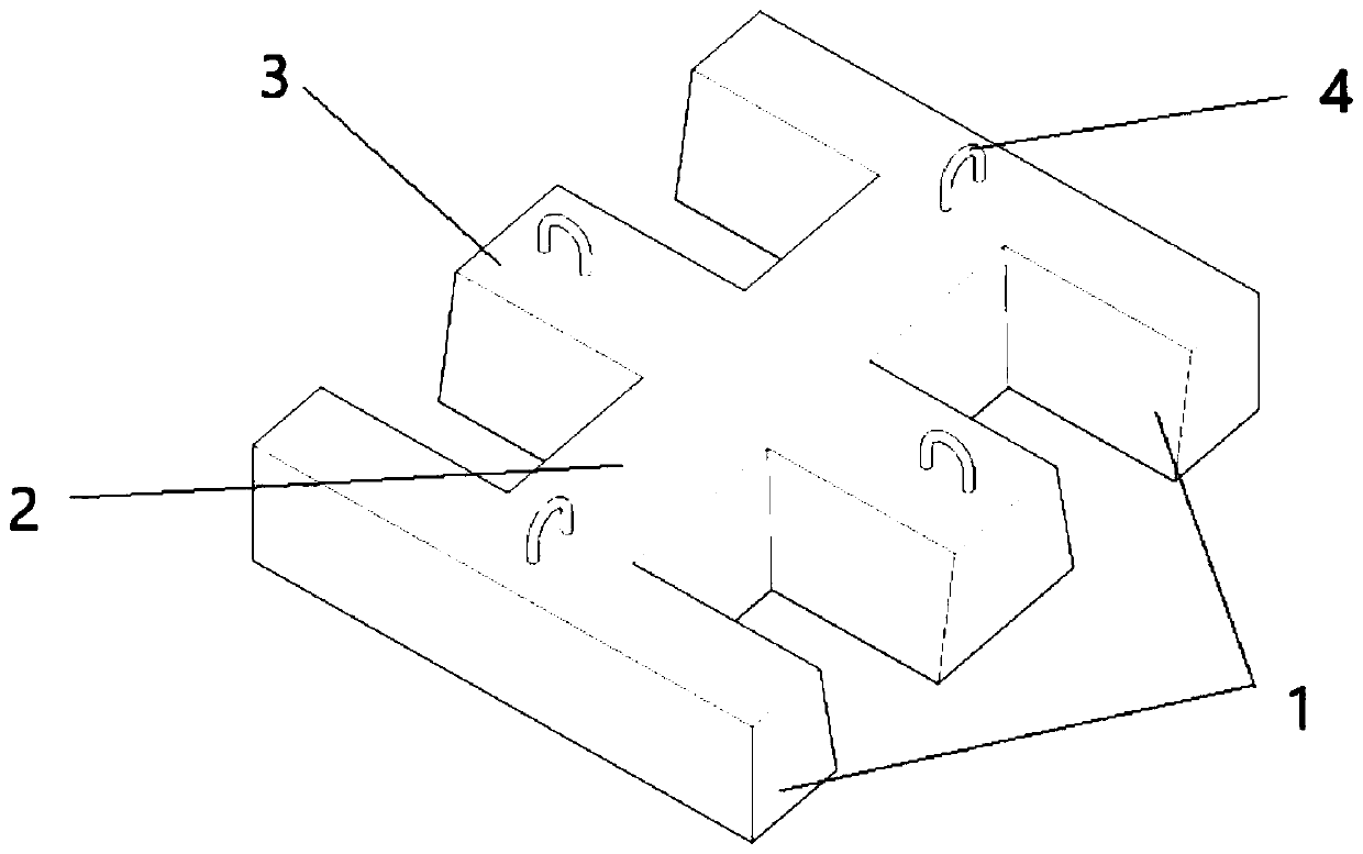
[0038] combine figure 1 and figure 2 , a slope protection plate, comprising an end plate 1, a longitudinal plate 2 and a middle plate 3, the end plate 1, the longitudinal plate 2 and the middle plate 3 are elongated concrete plates, the end plate 1, the longitudinal plate 2 and the middle plate 3 The lengths of the end plates 1 and the middle plates 3 are equal in length, two end plates 1 are arranged in parallel, the longitudinal plates 2 are perpendicular to the end plates 1, and the longitudinal plates 2 are arranged between the two end plates 1 And connect the middle parts of the two end plates 1, one end of the longitudinal plate 2 is connected to the middle part of one end plate 1, the other end of the longitudinal plate 2 is connected to the middle part of the other end plate 1, and the middle plate 3 is arranged between the two end plates 1 , the middle plate 3 is parallel to the end plate 1, the middle part of the middle plate 3 is fixedly connected with the longitu...

Embodiment 2

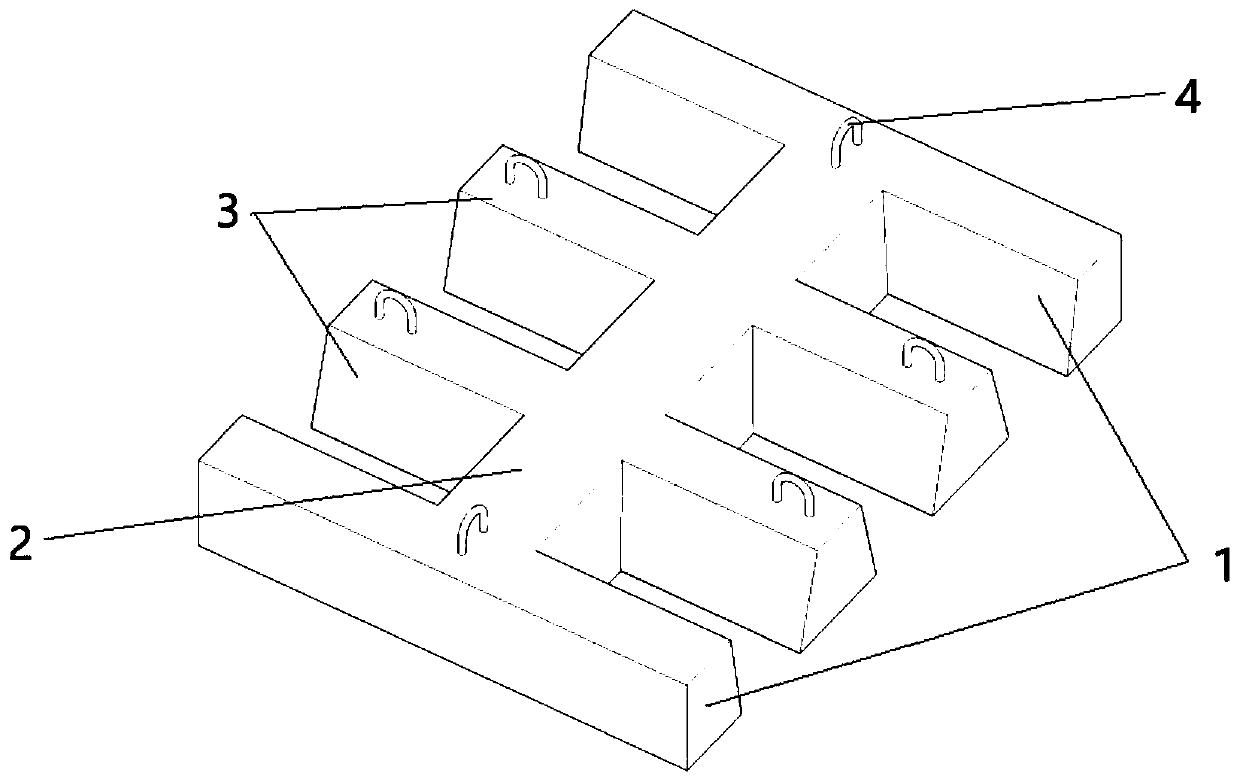
[0045] combine image 3 The difference between this embodiment and Embodiment 1 is that the number of intermediate plates 3 is different. In this embodiment, there are two intermediate plates 3, and the distance between the two intermediate plates 3 is the same as that between the end plate 1 and the end plate 1 to The intervals between adjacent middle plates 3 are the same, and the middle parts of the two middle plates 3 are connected with the longitudinal plates 2 . In this arrangement, increasing the number of intermediate plates 3 can correspondingly increase the number of tie rods 4 on the intermediate plates 3, so that the connection between slope protection plates can be more stable.

Embodiment 3

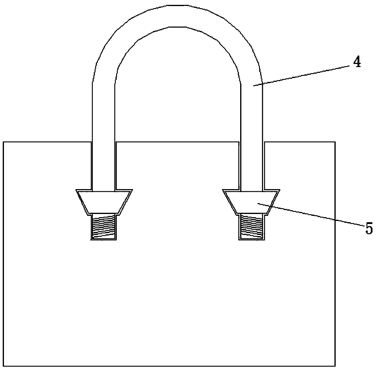
[0047] combine Figure 4 , This embodiment differs from Embodiment 1 in that the structure of the pull rod 4 is different.

[0048]In this embodiment, the two ends of the pull rod 4 are respectively provided with bending parts 41, which are formed by bending two straight rods of the pull rod 4, and the bending angle can be 90° or 180°. Located in the end plate 1, the longitudinal plate 2 or the middle plate 3, the bent portion 41 can effectively increase the firmness of the tie rod 4, and has the advantages of simple production, good firmness and low production cost.


PUM


Abstract

The embodiment of the invention discloses a slope protection plate and a flexible connection protection face system, and relates to the technical field of slope protection structures. According to thetechnical scheme, the slope protection plate is characterized in that the slope protection plate comprises end plates, a longitudinal plate and a middle plate; the two end plates are arranged in parallel; the longitudinal plate is perpendicular to the end plates, is arranged between the two end plates and is connected with the middle portions of the two end plates; the middle plate is arranged between the two end plates and is parallel to the end plates. The middle portion of the middle plate is fixedly connected with the longitudinal plate. Pull rods are arranged at the connection positionsof the longitudinal plate and the end plates and the two ends of the middle plate correspondingly. Each pull rod is of an n-shaped structure. The end portions of the pull rods are fixed. The effects of improving integrity and flexibility of protection faces, lowering the requirements for large hoisting equipment, improving transportation convenience and reducing production and use cost are achieved.

Description

technical field [0001] Embodiments of the present invention relate to the technical field of slope protection structures, in particular to a slope protection board and a flexible connection surface protection system. Background technique [0002] In port engineering, in order to protect rockfill structures, breakwaters and bank revetments, protective blocks or large stones are generally used as protective surfaces and to protect against waves. There are many types of commonly used prefabricated blocks, including twisted I blocks, twisted king blocks, four-legged hollow blocks, square pyramids and fence panels. Among them, since the fence board appeared as a new type of protective block, it is very popular because of its beautiful appearance and convenient construction. At the same time, he has accumulated rich theoretical and practical experience. Its disadvantages are: [0003] ① Due to the use of a single layer, any plate in the armor will lose its stability (slip down,...

Claims


Application Information

Patent Timeline
Patent Type & Authority Applications(China)
IPC IPC(8): E02B3/14
CPCE02B3/14
Inventor 杨亚洲
Owner 杨亚洲
Why Eureka
Try Eureka