Low-noise low-energy-consumption refrigerating system and working method thereof

A refrigeration system and low-energy consumption technology, applied in refrigerators, refrigeration components, refrigeration and liquefaction, etc., can solve the problem that the amount of liquid in the pipeline at the outlet of the evaporator cannot be guaranteed, the heat exchange length between the return pipe and the capillary is limited, and the refrigerant The gas is prone to overheating and other problems, which can increase the difficulty of product processing, improve the cooling capacity and operating efficiency, and have obvious advantages in energy saving and emission reduction.

Inactive Publication Date: 2020-01-21
XI AN JIAOTONG UNIV
View PDF3 Cites 9 Cited by
  • Summary
  • Abstract
  • Description
  • Claims
  • Application Information

AI Technical Summary

Problems solved by technology

[0004] In fact, this scheme of using the low-temperature refrigerant gas in the return air pipe to supercool the refrigerant in the capillary also has shortcomings. First, the refrigerant inside the evaporator is relatively dry, and the amount of liquid carried in the pipeline at the outlet of the evaporator cannot Guaranteed, the heat transfer of the entire evaporator is limited, and the refrigerant gas in the return air pipe is easily overheated and cannot provide enough cooling capacity for subcooling
Secondly, the length of the heat exchange between the return air pipe and the capillary is limited, and part of the supercooled refrigerant will still produce a large amoun

Method used


Image

  • Low-noise low-energy-consumption refrigerating system and working method thereof
  • Low-noise low-energy-consumption refrigerating system and working method thereof

Examples


Embodiment Construction

[0014] The present invention will be described in further detail below in conjunction with the accompanying drawings and specific embodiments.

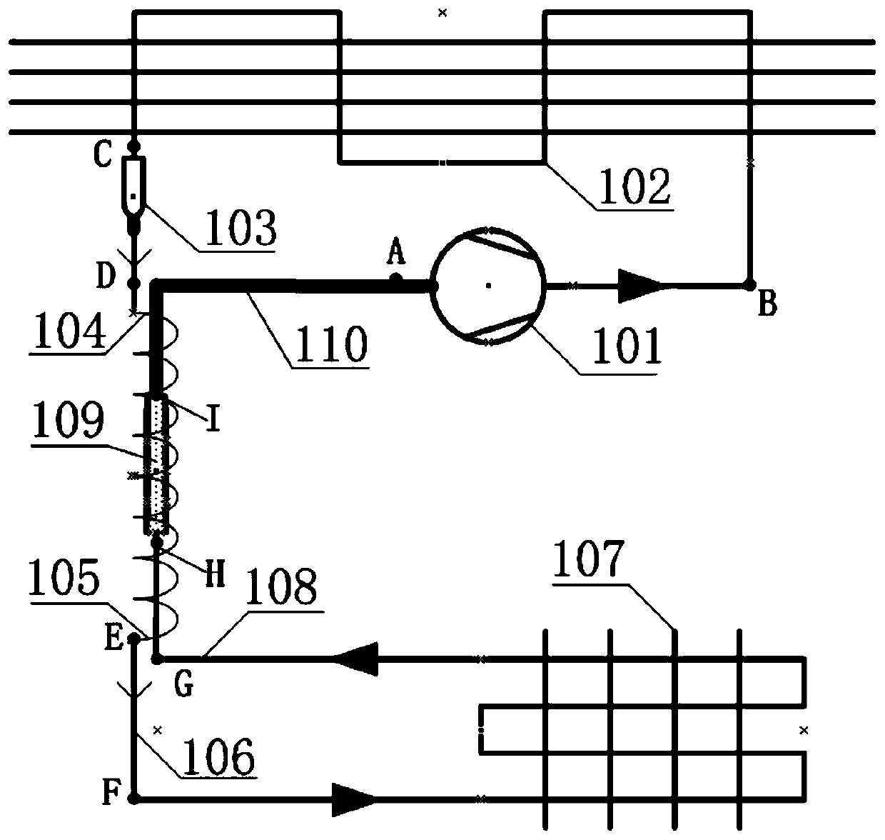
[0015] Such as figure 1 As shown, the present invention is a refrigeration system with low noise and low energy consumption. The outlet of the compressor 101 is connected to the inlet of the condenser 102, the outlet of the condenser 102 is connected to the inlet of the dry filter 103, and the outlet of the dry filter 103 is connected to the capillary inlet section 104. , the capillary outlet section 105 is connected to the evaporator inlet pipe 106, the evaporator inlet pipe 106 is connected to the evaporator 107, the evaporator 107 is connected to the evaporator outlet pipe 108, the evaporator outlet pipe 108 is connected to the inlet of the low pressure liquid reservoir 109, and the low pressure The outlet of the liquid reservoir 109 is connected with the inlet of the gas return pipe 110 . Among them, the outer wall surface of the...


PUM


Abstract

The invention discloses a low-noise low-energy-consumption refrigerating system and a working method thereof. The refrigerating system comprises a compressor, wherein an outlet of the compressor is connected with an inlet of a condenser; an outlet of the condenser is connected with an inlet of a drying filter; an outlet of the drying filter is connected with an inlet section of a capillary tube; an outlet section of the capillary tube is connected with an inlet tube of an evaporator; the inlet tube of the evaporator is connected with the evaporator; the evaporator is connected with an outlet tube of the evaporator; the outlet tube of the evaporator is connected with an inlet of a low-pressure liquid storage device; an outlet of the low-pressure liquid storage device is connected with an inlet of an air return tube; the outer wall surface of the capillary tube between the inlet section of the capillary tube and the outlet section of the capillary tube is sequentially attached to the outer wall surfaces of the outlet tube of the evaporator, the low-pressure liquid storage device and the air return tube; and an outlet of the air return tube is connected with the compressor. Accordingto the low-noise low-energy-consumption refrigerating system and the working method thereof, a multi-section heat return mode is utilized, so that the dryness of a refrigerant at the outlet of the capillary tube is reduced, and the energy consumption of the system is reduced while the noise of the refrigerating system is reduced.

Description

technical field [0001] The invention belongs to the technical field of refrigeration, and in particular relates to a refrigeration system with low noise and low energy consumption and a working method thereof. Background technique [0002] Refrigerators and freezers are indispensable refrigeration and refrigeration equipment in modern life. At present, the common refrigerators and freezers are all based on the vapor compression refrigeration technology to achieve the purpose of refrigeration. For reasons of cost and operational stability, the throttling mechanism of this type of technology generally adopts capillary tubes. However, in daily use, a refrigeration system that uses a capillary tube as a throttling mechanism will generate irregular noise with a very large fluctuation range of sound pressure level at the outlet of the capillary tube or the inlet of the evaporator, and the user experience is extremely poor. The reason for the noise here can be explained as: in th...

Claims


Application Information

Patent Timeline
IPC IPC(8): F25D11/00F25B1/00F25B43/00F25B41/06F25B41/37
CPCF25D11/00F25B1/00F25B43/003F25B43/006F25B41/37
Inventor 刘晔鱼剑琳晏刚
Owner XI AN JIAOTONG UNIV
Why Eureka
Try Eureka