Microfluidic Negative Pressure Driven Normally Open Microvalve

A microfluidic, negative pressure technology, applied in valve devices, engine components, mechanical equipment, etc., can solve problems such as large deformation and high output change, and achieve the effect of high safety and reliability

A microfluidic, negative pressure technology, applied in valve devices, engine components, mechanical equipment, etc., can solve problems such as large deformation and high output change, and achieve the effect of high safety and reliability

CN110726002BActive Publication Date: 2021-08-06CHINA JILIANG UNIV

Image

  • Microfluidic Negative Pressure Driven Normally Open Microvalve
  • Microfluidic Negative Pressure Driven Normally Open Microvalve
  • Microfluidic Negative Pressure Driven Normally Open Microvalve

Examples


Embodiment Construction

[0027] The present invention will be described in detail below in conjunction with the accompanying drawings and specific embodiments, wherein the schematic embodiments and descriptions are only used to explain the present invention, but not as improper limitations to the present invention.

[0028] It should be noted that, in the case of no conflict, the embodiments in the present application and the features in the embodiments can be combined with each other. The present invention will be described in detail below with reference to the accompanying drawings and examples.

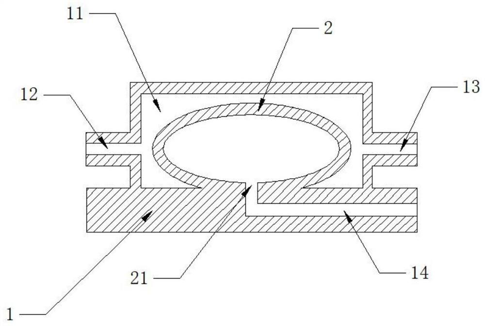
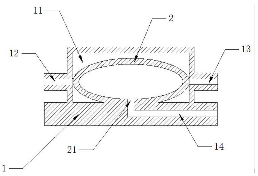
[0029] Such as figure 1 As shown, the present invention discloses a structural schematic diagram of a negative pressure driven normally open microvalve. It has the structural characteristics of a microfluidic mold cavity microvalve. The structure mainly includes a valve body 1 and a valve core 2, the valve body 1 is provided with a valve cavity 11, and the valve cavity 11 is provided with a normally open...


PUM


Abstract

The invention discloses a normally open micro-valve driven by microfluidic negative pressure, which comprises a valve body and a valve core. In the cavity, the valve core is hollow inside, and the valve core is deformed with the pressure inside and outside the valve core. There is a negative pressure input port on the valve core. / or the output end is blocked to close the valve. In the present invention, the negative pressure signal controls the on-off of the positive pressure signal, which can bring large deformation and high output variation; it is mainly used in microfluidic chips, with higher safety and reliability, and is easy to implement in similar digital circuits. Grounding, signal gain and other functions realize various functions such as NOT gate, AND gate and OR gate, and high-level applications such as storage and oscillation of pneumatic signals can be realized through the design method of equivalent circuit.

Description

technical field [0001] The invention relates to a digital microfluidic pressure logic control chip, and mainly relates to a microfluidic negative pressure driven normally open microvalve. Background technique [0002] Digital microfluidics is a new type of pneumatic logic control technology that has emerged in recent years. With the development of modern robot systems towards bionics and flexibility, especially the emergence of pneumatic flexible actuator structures, it has wider applications. By constructing a microvalve array system with digital logic, the technology regards the microvalve as a transistor in a digital circuit, and regards the flow channel as a wire, so that the signal of the output channel can be controlled and adjusted according to the logic of the input signal, where the input signal can be It is the air pressure, and it can also be the corresponding hydraulic signal. However, its output signal has always been a negative vacuum pressure. For the current...

Claims


Application Information

Patent Timeline
06 Aug 2021
Publication
CN110726002B
IPC
F16K99/00
CPC
F16K99/0015; F16K99/0059
Inventors
周洲; 张昆鹏