
Optical module

A technology of optical modules and sub-modules, applied in the field of optical communication, can solve the problems of affecting the coupling efficiency, failing to meet the lower limit requirements of the output optical power of optical modules, and affecting the quality of data communication, etc.

Active Publication Date: 2020-01-24
HISENSE BROADBAND MULTIMEDIA TECH
View PDF7 Cites 6 Cited by
  • Summary
  • Abstract
  • Description
  • Claims
  • Application Information

AI Technical Summary

Problems solved by technology

In the optical module assembly process, due to the processing tolerance of the isolator itself, after passive assembly, there will be a relatively large angular deviation between the actual bias direction of the isolator and the polarization direction of the light emitted by the optical transmitter. Between 10° and 15°, which will affect the coupling efficiency, which will easily lead to the failure to meet the lower limit of the output optical power of the optical module; in addition, for some products with upper limit requirements for optical power, if the power When the upper limit of the output optical power of the optical module is exceeded, the current method usually used is to reduce the output optical power of the optical module by changing the relative position between the optical transmitter and the optical fiber, but this method will bring the output optical power of the optical module Easy to fall and other problems, affecting the quality of data communication

Method used


Image

  • Optical module
  • Optical module
  • Optical module

Examples


Embodiment Construction

[0033] The following will clearly and completely describe the technical solution in this embodiment with reference to the drawings in this embodiment. Obviously, the described embodiment is only a part of the embodiments of the present invention, but not all of them. All other embodiments obtained by persons of ordinary skill in the art based on the embodiments in this application without creative efforts fall within the protection scope of the present invention.

[0034] One of the core links of optical fiber communication is the conversion of photoelectric signals. Optical fiber communication uses optical signals carrying information to be transmitted in optical fibers / optical waveguides, and low-cost, low-loss information transmission can be achieved by using the passive transmission characteristics of light in optical fibers. However, information processing equipment such as computers use electrical signals, which requires mutual conversion between electrical signals and o...


PUM


Abstract

The application provides an optical module, wherein an optical transceiver secondary module in the optical module includes a round square tube body, an isolator, an adjustment connecting component andan optical emitter; one end of the adjustment connecting component embedded into the round square tube body is connected with the isolator, and one end of the adjustment connecting component arrangedoutside of the round square tube body is in rotatable sleeve connection with the optical emitter. Through adoption of the technical scheme of the optical module, the adjustment connecting component is rotated from the outside of the round square tube body, then the isolator in the round square tube body can rotate along with the adjustment connecting component, thus adjustment of a coupling powerbetween the optical emitter and the isolator can be achieved through adjustment of an included angle between a polarization direction of a laser emitted by the optical emitter and a polarization direction of the isolator, and finally, control of an output optical power of the optical module can be achieved; in addition, as there is no need to change a relative position between the optical emitterand an optical fiber adapter, the optical fiber adapter is fixed directly during packaging, thus a packaging process is simplified, and stability of the output optical power of the optical module also can be ensured.

Description

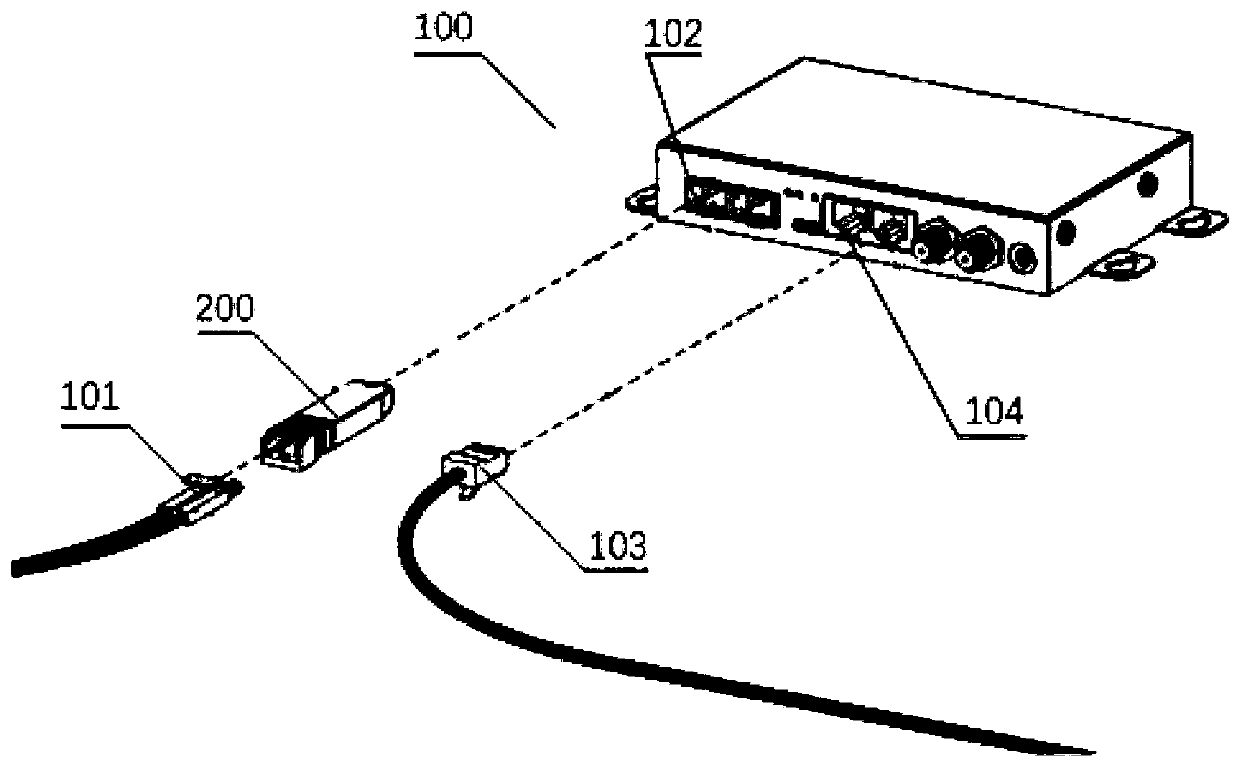
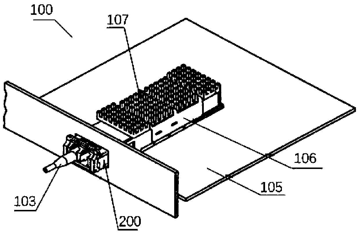
technical field [0001] The present application relates to the technical field of optical communication, and in particular to an optical module. Background technique [0002] Optical transceiver integrated module, referred to as optical module, is a standard module in the field of optical communication equipment. A standard optical module usually includes a light emitting sub-module, a light receiving sub-module, a microprocessor and other devices. In addition, there are some optical modules that package a separate light emitting sub-module and a light receiving sub-module in a metal case to form a bidirectional The optical sub-module is also called an optical transceiver sub-module. [0003] Wherein, the optical transmitting sub-module (or optical transceiver sub-module) mainly includes an optical transmitter. In addition, in order to realize the isolation of reflected light in the optical path, an isolator is usually provided on the light output side of the optical transmi...

Claims


Application Information

Patent Timeline
Patent Type & Authority Applications(China)
IPC IPC(8): G02B6/42
CPCG02B6/4208
Inventor 蔚永军张晓廓张海祥
Owner HISENSE BROADBAND MULTIMEDIA TECH
Learn More